This Drill Bushing Guide from Carr Lane Mfg. provides detiled information about the various applications, installation methods, and features of the different types of drill bushings. Information in this guide is adapted from the Carr Lane Mfg. Co Jig & Fixture Handbook.
Drill Bushings Guide Appendix:
If you know which drill bushing details and information you are searching for in this guide, select the topic below to navigate to that section:
What is a Drill Bushing?
What is a Drill Bushing?
Drill bushings are a major element in most of today’s drill jigs. They act as precision guiding devices for drills, reamers, taps, counterbores, and similar shank-mounted cutting tools. Drill bushings serve three purposes: they locate, guide, and support the cutting tool.
Although they serve mainly as guides for cutting tools, drill bushings also have other uses. They work well in assembly tools, inspection tools, and similar devices that require precise alignment and location of cylindrical parts.
The most common cutting tool for drilling is the twist drill. The design and cutting characteristics of the standard twist drill, although efficient, are not well suited for precision machining. The major reasons are found in the construction of the twist drill.
Twist drills have two angled cutting edges. The cutting edges are usually set 118º apart with a lip clearance angle of approximately 12º. The point formed by these angles is called the “chisel edge.” The chisel edge is normally at 135º to the cutting edges of the drill. This design, although highly efficient for cutting, is not effective for centering the tool.
In addition, the material removed to form the flutes and margins of the drill, combined with the standard back taper, greatly reduces the contact area between the twist drill and the hole. The problems of the design increase further because of the unsupported length of the drill. Also, in most production situations, the drill point is not always precisely centered. A drill with an off-center point cuts oversized holes.
When combined, these conditions result in drilled holes that are off center, oversize, out of round, out of alignment, and usually not straight. But simply supporting the twist drill in a drill bushing can greatly reduce, if not eliminate, most of these problems.
Types of Standard Drill Bushings
Types of Standard Drill Bushings
Drill bushings come in a wide range of types and styles. The three general categories of drill bushings available are permanent bushings, renewable bushings, and air-feed-drill bushings.
As show in Figure 10-1, drill bushings are identified by letters and numbers. These letters and numbers describe the basic form and specific sizes of each bushing, in a format established by the American National Standards Institute (ANSI). This format consists of one to four letters to identify the bushing type, an OD size in 64ths of an inch, a length size in 16ths of an inch, and the ID of the bushing stated to four decimal positions.
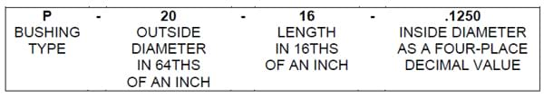 Figure 10-1. Drill bushings are specified by ANSI letter-and-number designations, which identify the bushing type and specific dimensions.
Permanent Drill Bushings
Permanent bushings are intended for limited-production applications where bushings are not regularly changed during the service life of the workholder.
Permanent bushings are either pressed directly into the jig plate or cast in place. Since these bushings are permanently installed, repeated replacement would cause the mounting hole to wear and reduce the accuracy and soundness of the installation.
The different varieties of permanent bushings can be found below.
Press-Fit Bushings
Press-fit bushings, Figure 10-2, are the most common and least expensive permanent bushing. These bushings are identified by the letter P (or PC when the bushing is carbide).
Press-fit bushings are designed for one-step operations, such as drilling or reaming. The bushings are pressed directly into the jig plate. They are held in place by the force of the press fit. Figure 10-3 shows recommended hole size for pressfit bushings.
The headless design allows the bushings to be mounted close together and flush with the top of the jig plate. This design, however, offers less resistance to heavy axial loads.
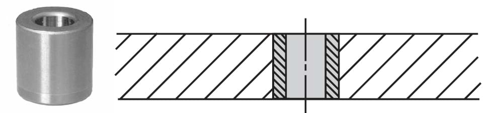 Figure 10-2. Plain press-fit bushings, for permanent installations, are the most popular and least expensive drill bushings.
Head-Press-Fit Bushings
Head-press-fit bushings, Figure 10-4, are similar to the press-fit bushing in design and application. These bushings, however, are made with a head. Head-press-fit bushings are designed for applications where heavy axial loads might push a press-fit bushing through the mounting hole. The headpress- fit bushings are types H or HC (carbide) bushings. These bushings can be mounted with head exposed, as shown, or counterbored if the bushing must be mounted flush with the top of the jig plate. When the jig plate is counterbored, only the body diameter of the bushing provides the location and only this diameter needs to be reamed. The counterbored area provides clearance for the head and should not be a precision fit. Figure 10-5 shows standard head diameters. The length of the bushing is measured from the underside of the head to the exit end of the bushing.
 Figure 10-3. Recommended hole sizes for press-fit bushings in unhardened steel or cast iron jig plates.
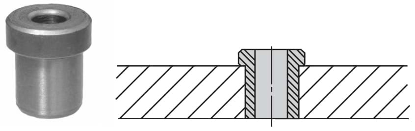 Figure 10-4. Head-type press-fit bushings have a head to resist heavy axial loads.
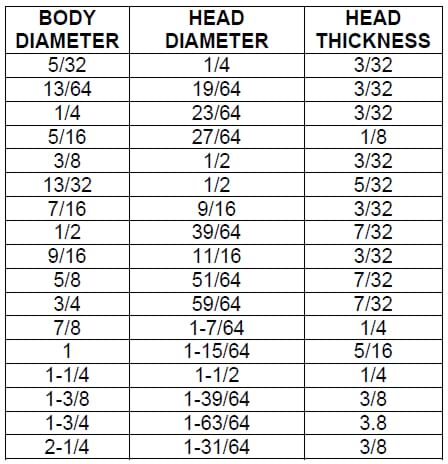 Figure 10-5. Dimensions of head-type press-fit bushings.
Serrated Press Fit Bushings
Serrated-press-fit bushings, type SP, shown in Figure 10-6, are used for applications where a hardened drill bushing is mounted in a soft jig plate. The bushings have an eternal mounting surface with both a precision-ground diameter and a serrated, or straight-knurled, area. The ground portion aligns the bushing in the mounting hole in the same way a press-fit bushing does. The serrations prevent any rotational movement from high-torque loads. The serrations also resist axial loads that could push the bushing through the jig plate. These bushings are well suited for jig plates made from aluminum, magnesium, Masonite, wood, or similar soft materials.
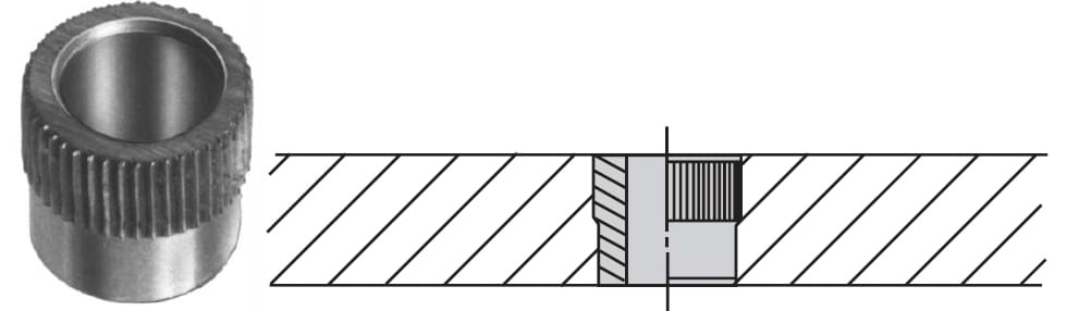 Figure 10-6. Serrated-press-fit bushings have serrations on top to prevent rotation in soft materials, such as aluminum.
Serrata Groove Bushings
Serrata-groove bushings, type SG, Figure 10-7, are similar to the serrated-press-fit bushing. They do not, however, combine a precision diameter and serrations. Instead, the serrata-groove bushings are serrated over their entire length. The serrations and grooves cut around the circumference of these bushings suit them for either pressed-in or cast-in-place applications. These bushings offer high torque resistance, but due to their straight-knurled mounting surface, they have a reduced resistance to axial loads. Similarly, since the circumference of these bushings is serrated and not ground, the internal diameter must be used to align the bushing for cast-in-place applications.
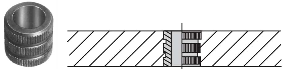 Figure 10-7. Serrata-groove bushings have full-length straight serrations for cast-in-place or potted installations.
Diamond Groove Bushings
Diamond-groove bushings, type DG, are another form of bushing for cast-in-place applications. As shown in Figure 10-8, these bushings resemble the serrata-groove bushing, but they have a diamond pattern knurl rather than straight pattern knurl on the circumference. The diamond knurl offers high resistance to both rotational and axial forces. Like the serrata-groove bushings, the circumference of the diamond-groove bushings are knurled and not ground, so the internal diameter must be used to align the bushing for cast-in-place applications.
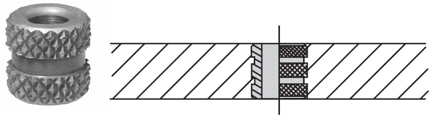 Figure 10-8.Diamond-groove bushings have a diamond-knurled OD for cast-in-place or potted installations subject to heavy axial loads.
Diamond-groove bushings should not be used for press-fit applications. For press-fit applications, straightserrated bushings are better because when they are pressed into the jig plate, the material displaced by the points of the knurl is moved into the area between the points. A diamond-pattern knurl, on the other hand, will cut the materials and actually broach the hole larger.
For cast-in-place applications, the bushings are mounted in holes that have a larger diameter. The space between the outer surface of the bushing and the inside of the hole is filled either with an epoxy resin or a lowmelting- point alloy, Figure 10-9.
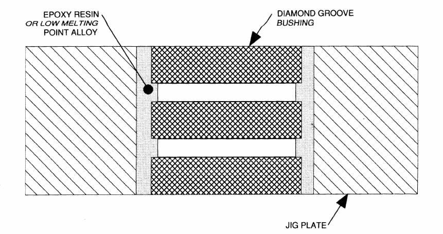 Figure 10-9. Diamond-groove bushings have a diamond-knurled OD for cast-in-place or potted installations subject to heavy axial loads.
Template Bushings
Template bushings, type TB, Figure 10-10, are designed for thin jig plates. These bushings permit larger diameter tools to be used with a thin jig plate. Rather than using a thicker jig plate normally required to support larger diameter drills, template bushings provide the necessary drill support in jig plates from 1/16” to 3/8” thick. This reduces both the cost and the weight of the jig plate.
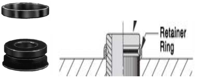 Figure 10-10. Template bushings are for thin template jig plates 1/16” to 3/8” thick.
Template bushings are installed as shown in Figure 10-11. When locating template bushings, follow the minimum edge distances and hole spacings shown in Figure 10-12(a). Once properly located, the mounting hole is drilled and reamed .001” to .003” larger than the mounting diameter of the bushing. The hole is countersunk on the workpiece side to permit the bushing to seat .015” below the surface, Figure 10-12(b). The bushing is then inserted and pressed into the hole.
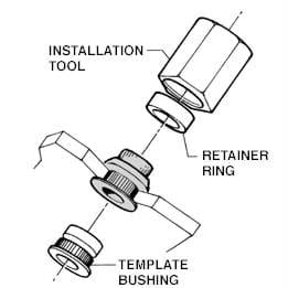 Figure 10-11. Template bushings are installed with an installation tool.
1. Laying Out Holes
Figure 10-11. Template bushings are installed with an installation tool.
1. Laying Out Holes
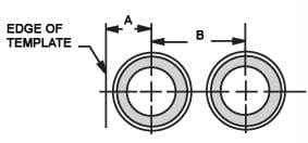 When laying out holes, observe the minimum hole spacing and edge distance listed below:
| BUSHING OD |
A MINIMUM |
B MINIMUM |
| 3/8 |
.60 |
.250 |
| 1/2 |
.73 |
.312 |
| 3/4 |
.98 |
.438 |
2. Creating a Countersink for a Ream Hole
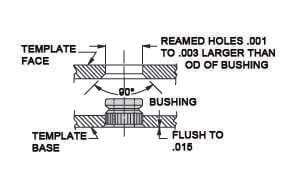 Ream hole .001 to .003 larger than bushing O.D. Countersink reamed hole to allow the bushing to seat .015 below flush with surface. For best results, use a piloted countersink tool so that the countersink is concentric and free of chatter marks.
3. Installing the Retainer Ring
Ream hole .001 to .003 larger than bushing O.D. Countersink reamed hole to allow the bushing to seat .015 below flush with surface. For best results, use a piloted countersink tool so that the countersink is concentric and free of chatter marks.
3. Installing the Retainer Ring
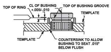 Install Retainer Ring with an arbor press whenever possible. The Installation Tool is also tapped for mounting on a rivet gun or other impact tool. Check that Retainer Ring top surface is within +.005/-.010 of the bushing groove’s top edge before installing.
Figure 10-12. Installation procedure for template bushings.
The retaining ring is mounted with the installation tool. When mounting the retaining ring, make sure the top of the ring is within +.005”/-.10” of the top of the groove in the bushing, Figure 10-12(c), before using the installation tool. The serrations on the bushing circumference prevent rotational movement. The retaining ring both locks the bushing in the jig plate and restricts any axial movement.
Circuit-Board Bushings
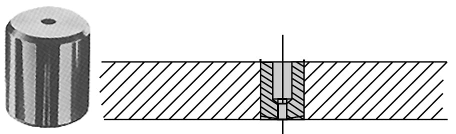 Figure 10-13. Circuit-board bushings are designed to accommodate the large shanks of circuit-board drills.
Renewable Drill Bushings
Renewable bushings are designed for applications where the bushings must be changed regularly during the service life of the workholder. Bushing changes are made when bushings wear out, or when multiple operations are performed in the same hole. With multiple operations, two or more drill bushings are used to produce the desired hole. The two principal forms of bushings for renewable installations are renewable drill bushings and liner bushings. The drill bushing locates and supports the cutting tool. The liner bushing locates and supports the drill bushing. Both the drill bushings and liner bushings for renewable arrangements are available in several styles.
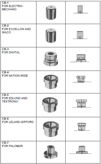 Figure 10-14. Circuit-board bushing variations.
Slip/Fixed Renewable
Slip/fixed renewable bushings, types SF and SFC (carbide), are the most common form of renewable bushings, Figure 10-15. This renewable bushing is the replacement for the older and obsolete slip renewable, type S, and fixed renewable, type F, bushings. Slip/fixed renewable bushings combine both the slip and fixed locking arrangements in the same bushing, Figure 10-16.
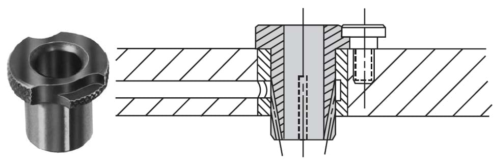 Figure 10-15. Slip/fixed renewable bushings are replaceable drill bushings used in high-volume production.
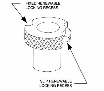 Figure 10-16. Slip/fixed renewable bushings are replaceable drill bushings used in high-volume production.
Slip/fixed renewable bushings are typically employed in long production runs where bushing changes are needed. These bushings can be installed in either a fixed-renewable or slip-renewable configuration by simply rotating the bushing, Figure 10-17.
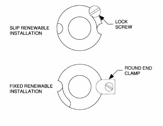 Figure 10-17. The slip/fixed renewable bushing can be installed as either fixed-renewable or slip-renewable by simply rotating the bushing.
The fixed-renewable installation is intended for single-step applications such as drilling or reaming. These bushings are changed only when the bushings wear. Fixed-renewable bushings are held in place with a lockscrew or round clamp. The clamps hold the bushing in place and prevent any movement during the machining cycle. When the bushing must be replaced, the clamp is removed and the bushing changed. The clamp is then reinstalled to securely hold the bushing.
Slip-renewable installations are convenient for applications when multiple operations are performed in the same hole. One example is drilling and reaming the same hole. The first slip-renewable bushing is installed, and the hole is drilled. The drilling bushing is removed. Then the reaming bushing is installed, and the hole reamed to size.
The slip-renewable side allows rapid changeover. The bushing is rotated clockwise to lock it in place and rotated counterclockwise for removal, Figure 10-18. A cutout at the end of the recess makes the bushing easy to remove and replace. This design ensures the rotation of the drill will not allow the bushing to back out of the hole. Although slip/fixed renewable bushings are normally installed in a liner bushing, they can also be installed directly in the jig plate. Figure 10-19 shows the recommended hole sizes for installing slip/fixed renewable bushings without a liner bushing.
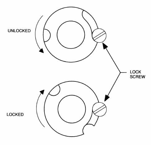 Figure 10-18. The slip-renewable bushing is rotated clockwise to lock it in place, and rotated counterclockwise for removal.
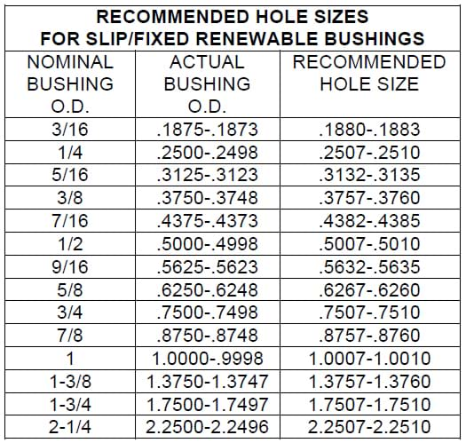 Figure 10-19. Recommended hole sizes for installing slip/fixed renewable bushings without a liner bushing.
Drill Bushings for Counterbores
The most effective amount of contact area between the bushing ID and the cutting tool is approximately one and one half times the diameter of the cutting tool. Added bearing surface, as it is called, can create more resistance to the drill, and also cause issues with chips building up inside the bushing causing premature wear, and even causing the drill to break. For these reasons, standard drill bushings with a length over this approximate one and half size will be counterbored at the top. This counterbored portion still provides adequate drill support, while alleviating possible issues of chip build up and drill breakage. The counterbore data chart, Figure 10-20, indicates which bushing lengths are counterbored, and which are not. These longer bushings may be ordered as “no counterbore” bushings, at an extra charge.
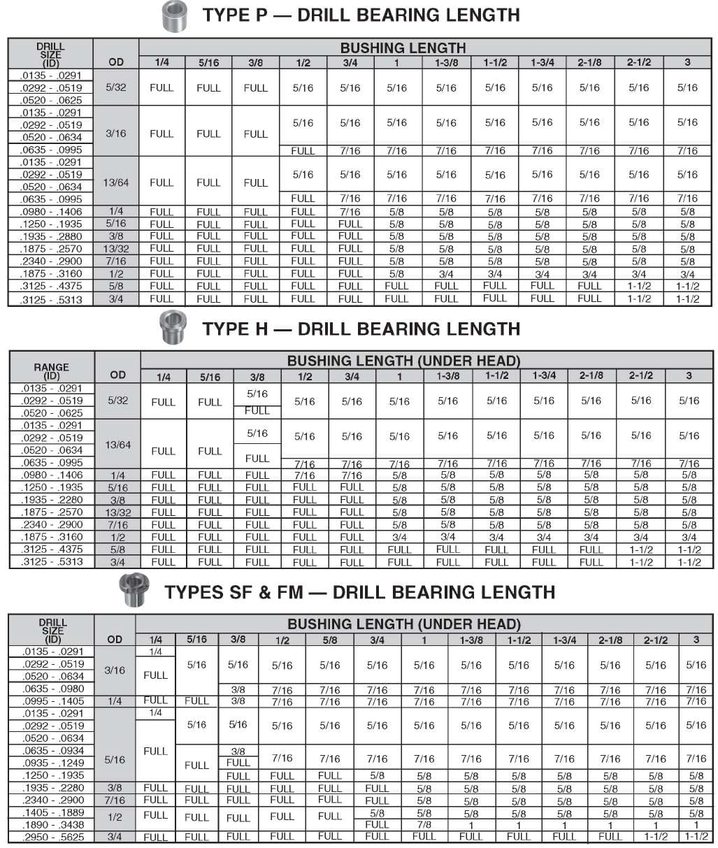 Figure 10-20. Long bushings for small drill sizes are slightly counterbored to prevent binding and heat buildup due to excessive bearing length.
Liner Bushings
Liner bushings, type L, Figure 10-21, resemble press-fit bushings, but are larger. Liner bushings are used with the renewable-style bushings to provide a hardened, wear-resistant hole in an otherwise-soft jig plate. The close sliding fit between the renewable bushing and the liner bushing permits the bushing to be changed repeatedly over long production runs with no loss of positional accuracy. The headless design of liner bushings allows them to be mounted close together and flush with the top of the jig plate. As with the press-fittype bushing, however, these bushings offer less resistance to heavy axial loads.
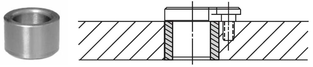 Figure 10-21. Liners are permanent bushings used to hold and locate renewable drill bushings.
Head Liner Bushings
Head-liner bushings, type HL, Figure 10-22, are similar to the liner bushing in design and application, but they are made with a head. Head-liner bushings, like head-press-fit bushings, are designed for applications where heavy axial loads might push a press-fit bushing through the mounting hole. These bushings can be mounted with the head exposed or counterbored, as shown. When the jig plate is counterbored for mounting, only the body diameter of the bushing provides the location and only this diameter needs to be reamed. The counter-bored area provides clearance for the head and should not be a precision fit. Figure 10-23 shows standard head diameters. Note: the length of a head-liner bushing is measured from the top to bottom of the bushing and includes the height of the head.
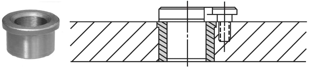 Figure 10-22.Head liners have a head to resist heavy axial loads.
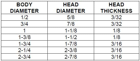
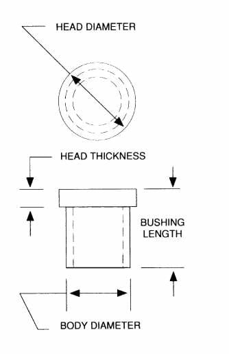 Figure 10-23. Dimensions of head-type liner bushings.
Lockscrews and Clamps
Renewable bushings are typically held in the jig plate with either a lockscrew or a clamp. The lockscrew or clamp both radially locates the bushing in the liner and holds the bushing in place. The lockscrew, Figure 10-24(a), is the most common form of locking device. These screws generally mount the bushings on either their slip-renewable or fixed-renewable sides. The screws are made with a shoulder under the head as shown. For mounting bushings on their slip-renewable side, the shoulder provides the necessary clearance needed to rotate the bushing for installation and removal. When mounted on the fixed-renewable side, the underside of the head securely holds the bushing in place.
The lockscrew locating jig, Figure 10-24(b), locates these lockscrews with respect to the renewable bushing. As demonstrated in Figure 10-24(c), the lockscrew locating jig is positioned against the bushing and struck with a hammer to mark the location of the lockscrew.
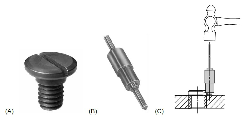 Figure 10-24. Lockscrews are the most common holding device for renewable bushings. The centerpunch shown is a multi-purpose locating jig for most lockscrews and clamps.
The round end clamp, Figure 10-25(a), can also be used for mounting bushings on either their slip-renewable or fixed-renewable sides. This clamp comes in two heights for bushing installations with either a recessed or projected liner, Figure 10-25(b).
 (A)
(A) 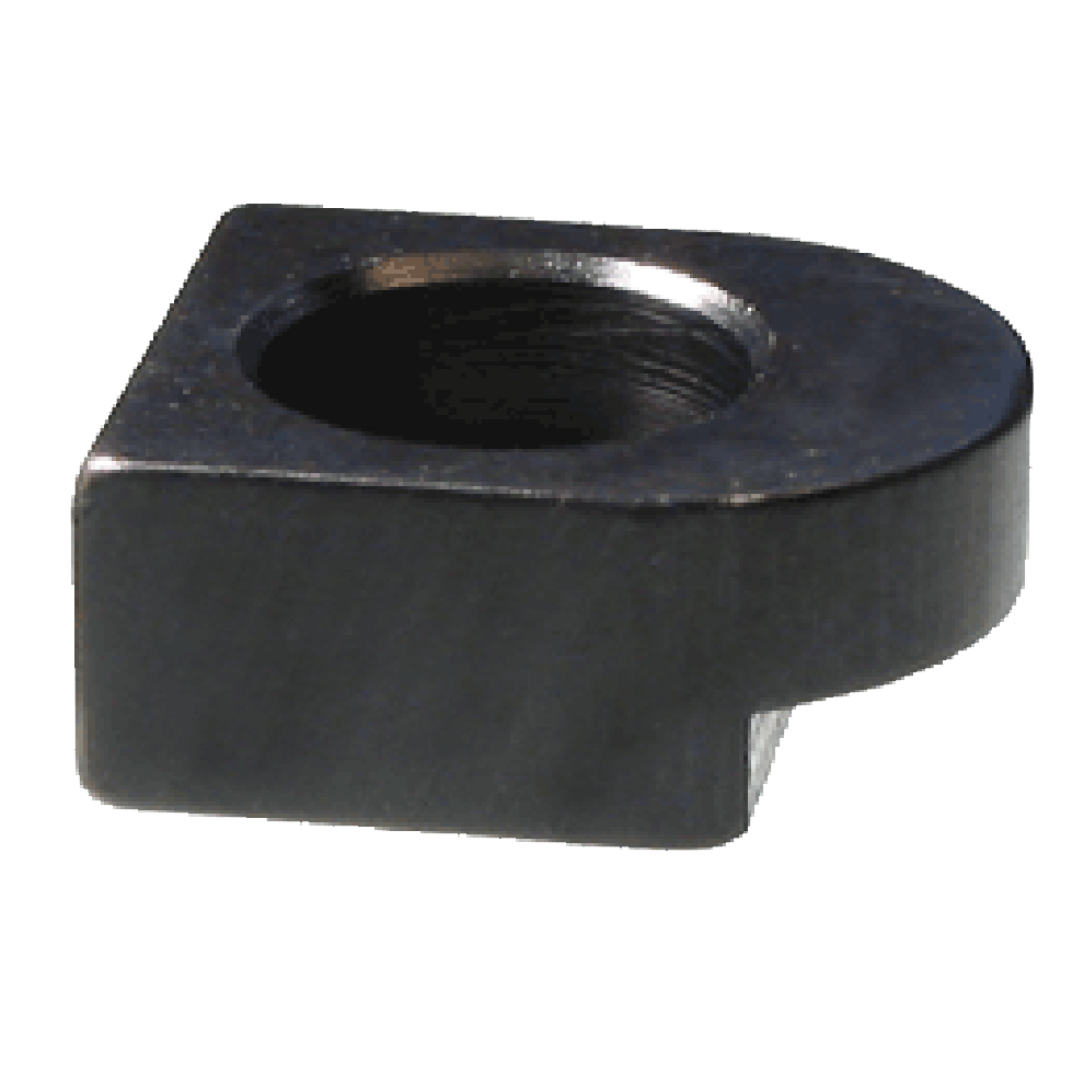 (B)
Figure 10-25. The round end clamp is a heavy-duty alternative to lockscrews.
(B)
Figure 10-25. The round end clamp is a heavy-duty alternative to lockscrews.
The round clamp is a bushing clamp designed specifically to hold bushings on their fixed-renewable side. As shown in Figure 10-26, round clamps are held in place with a socket-head cap screw. The lockscrew locating jig can also be used to install these clamps.
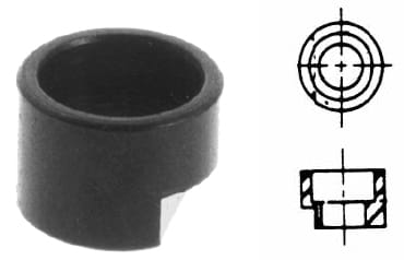
Figure 10-26. The round clamp is used to clamp bushings tightly on their fixed-renewable side.
The flat clamp, shown in Figure 10-27(a), is another form of bushing clamp. These clamps are used for the older styles of fixed-renewable bushings, which have a flat-milled clamping area. Like the round end clamp, the flat clamp is made in two heights for bushing installation with either a recessed or projected liner, Figure 10-27(b).
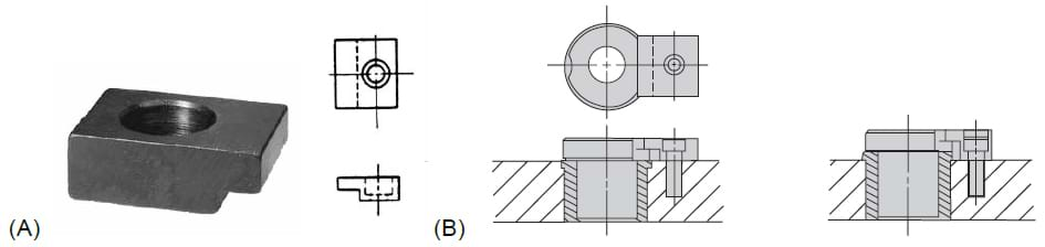 Figure 10-27. The flat clamp is a bushing clamp for the fixed-renewable bushings that have a flat-milled clamping area.
Locking Liner Bushing
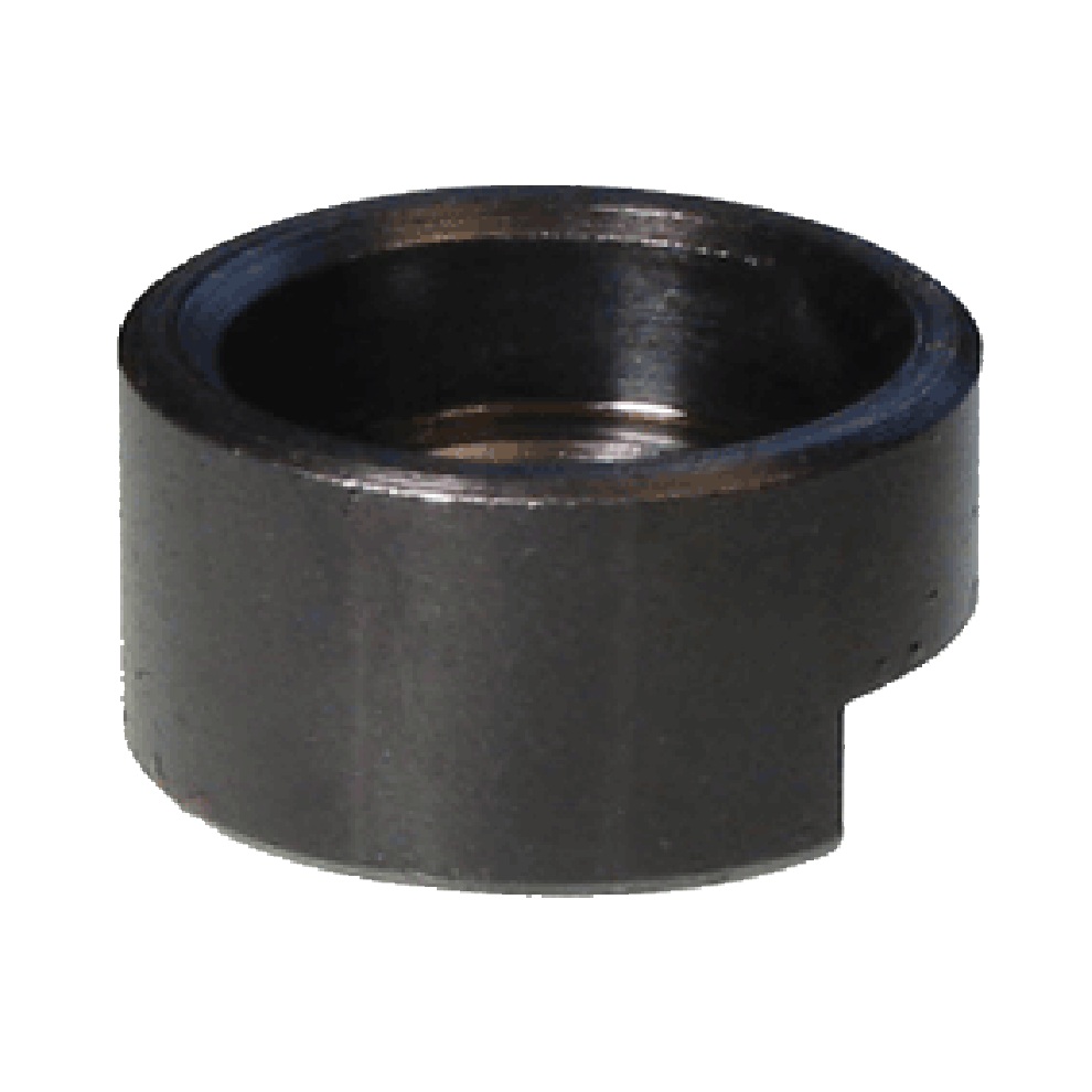
The locking liner bushing, type UL, Figure 10-28, is a unique bushing design for sliprenewable bushing installations. As show, the bushing combines both liner and locking device in a single unit. The basic design of this bushing is similar to a head liner, but it has a special locking tab that eliminates the need for a lockscrew. Locking liner bushings are slightly more expensive than the head-linerbushing/lockscrew unit they replace, but the reduced installation time more than offsets any additional cost. Note: these liners can only be used on the slip-renewable side.
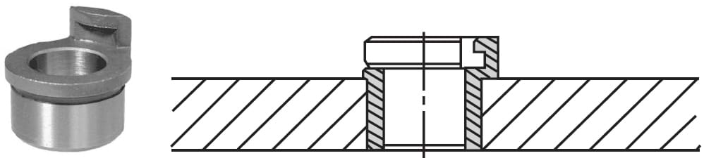 Figure 10-28. Locking liner bushings include a special locking tab that eliminates the need for a lockscrew. These liners can only be used for slip-renewable applications, not fixed.
Diamond-Knurled Locking Liner Bushing
The diamond-knurled locking liner bushing, type ULD, Figure 10-29, is a variation of the locking liner. These bushings are a form of liner bushing for cast-in-place applications. They combine both the liner and the locking device into a single unit, but the diamond-knurled locking liners have a diamond-pattern knurl on their circumference. The knurl offers high resistance to both rotational and axial forces. Like the other knurled bushings, the circumference of these liner bushings is not ground, so the internal diameter must be used to align the bushing for cast-in-place applications.
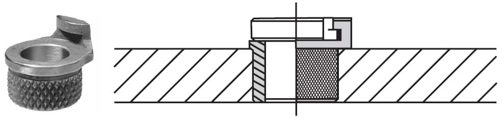 Figure 10-29. Diamond-knurl locking liner bushings are cast in place or potted.
EZ-Cast Liner Bushings
EZ-Cast liner bushings, type EZ, Figure 10-30, are another form of cast-in-place liner bushing. However, unlike the diamond-knurled locking liners, these bushings have an integral lockscrew and can be used to mount either side of slip/fixed renewable bushings.
The headless design of these liner bushings permits them to be mounted flush with the top of the jig plate.
The diamond-pattern knurl offers high resistance to both rotational and axial forces. Like other knurled bushings, the mounting surface of these bushings is not ground, so the internal diameter must be used to accurately align the bushing.
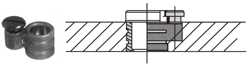 Figure 10-30. EZ-Cast liner bushings are cast-in-place liners that can be used for either slip- or fixed-renewable applications.
Gun-Drill Bushings
Gun-drill bushings, Figure 10-31, are specialty bushings for deep-hole-drilling machines. The type of bushing is determined by the type of gun-drilling machine.
Gun-drill bushings are similar to slip/fixed renewable bushings in both their appearance and application, but gun-drill bushings have the drill-bearing area at the head end of the bushing. Depending on the gun-drilling machine, these bushings are either one-piece or two-piece units.
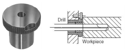 Figure 10-31. Gun-drill bushings are specially designed for gun-drilling machines (deep-hole drilling).
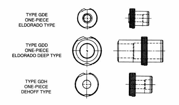 Figure 10-32. Variations of one-piece gun-drill bushings.
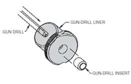 Figure 10-33. The gun-drill liner and gun-drill insert bushings are used together.
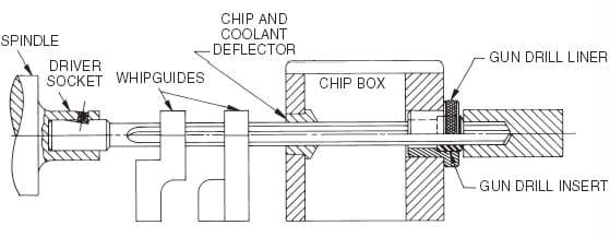 Figure 10-34. Typical gun-drilling setup.
The GD-type gun-drill bushing is a one-piece bushing. As shown in Figure 10-32, a third letter is added to the GD designation. This letter matches the bushing to a specific type of gun-drilling machine. The GDL (liner) and GDI (insert) bushings are two-piece units. As shown in Figure 10-33, these bushings are used together. Figure 10-34 shows the bushings in a typical gun-drilling setup.
Air-Feed-Drill Bushings
Air-feed-drill bushings are special-purpose bushings designed for a variety of commercial self-feeding air-feed drills, tappers, and back-spotfacers. These drill bushings, called “shanks,” are part of a complete system that includes the shanks, collars, and mounting devices. The shanks and collars are available either individually or as assembled units. When assembled, the unit is called an adaptor-tip assembly, Figure 10-35.
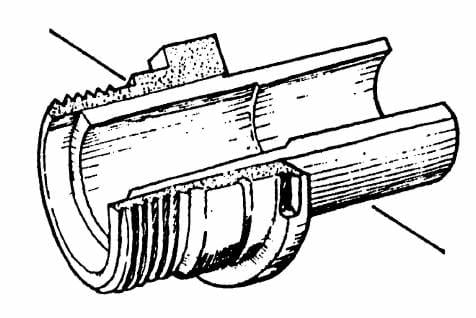 Figure 10-35. Adaptor-tip assemblies are the drill bushings mounted on air-feed drills.
The shanks, like standard bushings, are made with an internal diameter sized to fit the cutting-tool diameter, and an external diameter sized to fit the jig-mounted liner bushing. The collar is designed both to mount the tip assembly to the self-feeding drill motor, and to hold the complete unit in the jig-mounted liner bushing. As shown in Figure 10-36, the tip assembly is inverted in the liner and turned counterclockwise 30º to lock the units together. Figure 10-37 shows the various mounting options available for the jig-mounted liner bushings. The two primary forms of air-feed bushings are those for standard air-feed drills and those for coolant-type airfeed drills.
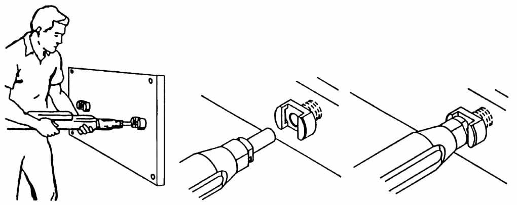 Figure 10-36. Air-feed drills are mounted by inserting the adaptor tip into a locking liner.
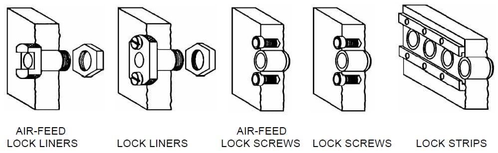 Figure 10-37. Liner-mounting options for air-feed-drill bushings.
Standard Bushings. Standard air-feed bushings, Figure 10-38, have a tip assembly made from individual shank and collar units. The collar attaches the unit to the air-feed-drill nosepiece either directly or through an optional reducer. The shank can have a plain end or a contour-nose design. The contour-nose shank is a modified standard shank for applications where curved or sloped surfaces are drilled. As shown in Figure 10-39, the contour-nose shank has a dual-angle angular relief, of 8º and 45º, on the end of the shank.
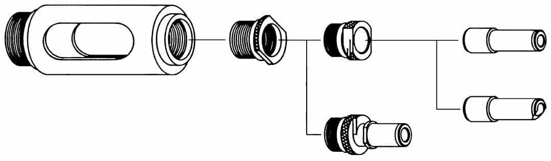 Figure 10-38. The nose assembly of an air-feed drill.
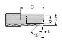 Figure 10-39. The contour-nose shank is modified for drilling curved or sloped surfaces.
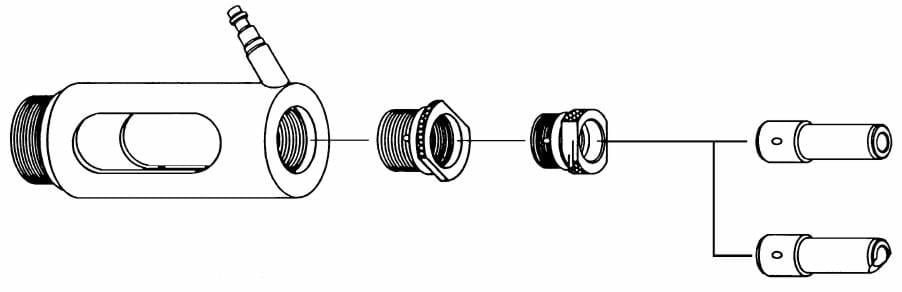 Figure 10-40. Coolant-induced bushings are similar to standard air-feed bushings, but have holes in each element to force coolant through the assembly to the cutting tool.
Coolant-Inducing Bushings. Coolant-inducing bushings, Figure 10-40, are essentially the same as standard air-feed bushings, except for the addition of drilled passages in each of the elements designed to force coolant through the assembly to the cutting tool. The air-feed-drill nose-piece is also different, as shown, to fit the connector for the coolant hose.
OPTIONAL FEATURES
Optional Features of Drill Bushings
In addition to the standard bushing variations, a range of optional features is also available for specific drilling situations. These optional features increase the versatility of the bushings and are useful in several ways.
Chip-Breaker
Chip-breaker bushings, type CH, Figure 10-41, are similar to the SF renewable-type bushings. These bushings, however, have a series of specially designed notches on the drill-exit end of the bushing. The notches break up chips created when tough or stringy materials are drilled.
Breaking up the chips reduces friction and heat buildup. In addition, chip breakers also reduce wear on the drill-exit end of the bushing and minimize any chance of damage to either the bushing or workpiece.
Chip breakers are also available on other bushing types, such as P and H bushings.
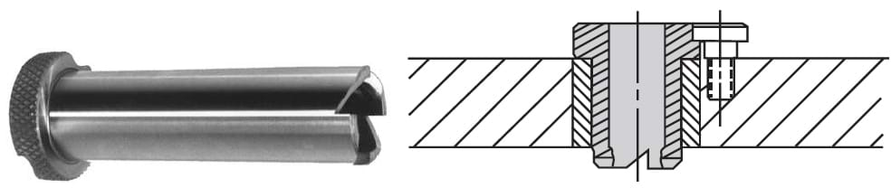 Figure 10-41. Chip-breaker bushings have specially designed notches on the drill-exit end for breaking chips.
Directed Coolant Passages
Directed-coolant bushings, Figure 10-42, are also similar to the SF renewable bushings. Directed-coolant bushings, type DC, come with coolant passages machined into the bushings which direct the coolant flow to the cutting area. This design both cools the cutting tool and washes away the accumulated chips.
Directed coolant bushings can be mounted in either DCL (liner) or DCHL (head liner) bushings, Figure 10-43. These special liner bushings have a unique design that directs the coolant flow from a drilled manifold passage, through the liner, to the holes in the bushing wall.
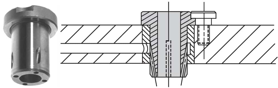 Figure 10-42. Directed-coolant bushings have drilled passages to direct coolant to the cutting area.
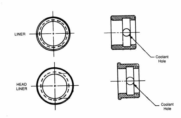 Figure 10-43. Directed-coolant liners are used with directed-coolant bushings.
Oil Grooves
Oil-groove bushings, Figure 10-44, ensure adequate cutting-tool cooling and lubrication. This style bushing is well suited for operations such as drilling hardened steel, where a constant supply of cutting oil is required.
Oil grooves are available in most bushing styles including the P, H, and SF renewable bushings.
The grooves are specially designed passageways cut into internal diameter wall of the bushing.
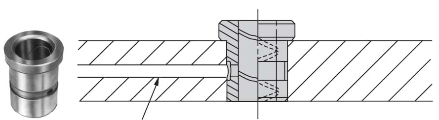 Figure 10-44. Oil-groove bushings have internal grooves that allow complete drill lubrication and cooling.
Oil-groove bushings are made with either an oil hole, an oil hole and external groove, or without an oil hole, Figure 10-45. The bushings with oil holes direct the oil flow from a drilled manifold passage. Bushings without an oil-feed hole use gravity to feed oil to the cutting tool through the head end of the bushing. There are 25 different groove patterns to fit virtually any requirement, Figure 10-46. End wipers, Figure 10-47, are also available to keep out dirt and chips. These wipers are for oil-groove patterns that do not break out at the wiper end.
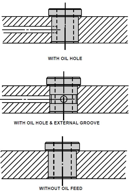 Figure 10-45. There are three general options for supplying fluid to the internal grooves.
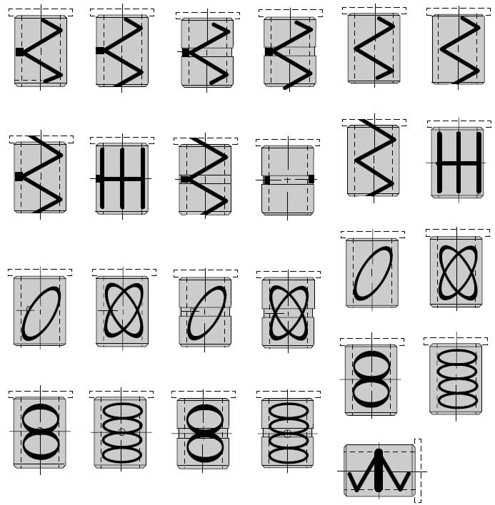 Figure 10-46. Oil-groove bushings are available in 25 different groove styles.
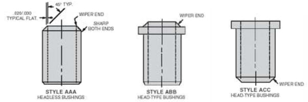 Figure 10-47. Oil-groove bushings are optionally available with wipers to guard against dirt and chips entering the inside.
Angled Exit Ends
Bushings should always be positioned so they offer maximum support for the cutting tool. Occasionally, with odd-shaped surfaces, this is not possible with standard bushings. So the exit end of the bushing must be modified or altered to match the specific shape of the workpiece surface.
Bushings with angled exit ends, Figure 10-48, are available for such conditions. Altering the shape of the exit end of the bushing affords the best support. It also prevents any lateral movement, or wandering, of the cutting tool.
Although almost-any-size cutting tool can move off the desired center position if improperly supported, this is especially true with smallerdiameter cutting tools.
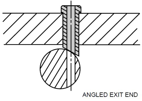 Figure 10-48. Angled-exit-end bushings are sometimes required, for drilling curved or sloped surfaces.
Ground Flats
Ground flats are typically specified for bushings that must be positioned close to each other in the jig plate.
Although almost any bushing can use ground flats, they are especially appropriate for headed bushings, as shown in Figure 10-49.
The ground flats permit standard bushings to be positioned very close together with a simple alteration.
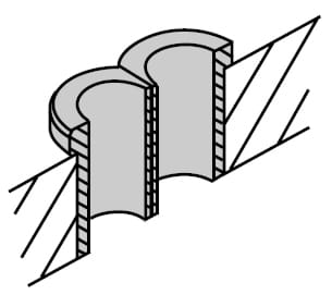 Figure 10-49. Ground flats can be used for positioning bushings close together.
Thinwall
Thinwall bushings, as their name implies, are drill bushings made with a very thin wall, Figure 10-50. These bushings are also used for applications where holes are close together.
One note of caution: Since the wall thickness is quite thin, these bushings will tend to follow the shape of the mounting hole. For this reason, the geometry of the mounting hole is very important to the accuracy of the installation.
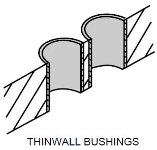 Figure 10-50. Thinwall bushings can also be used for positioning bushings close together.
Alternate Materials for Drill Bushings
Alternate Materials for Drill Bushings
Standard drill bushings are made of 1144 Stressproof steel. These are hardened to an RC 62-64 insidediameter hardness.
Other materials, such as 52100 steel, 300-series stainless steel, 400-series stainless steel, A2 tool steel, D2 tool steel, D3 tool steel, M2 tool steel, tungsten carbide, and bronze are also available for special situations.
When a Drill Bushing is used as a bearing surface Brass and Bronze are good options. Brass is softer than Bronze but typically contains higher amounts of lead. The lead in Brass provides lubrication to the bearing surface reducing wear. Bronze is typically lead-free while being softer than the steel part that typically passes through the bushing. In this way wear takes place in the bushing, not in the mating part. Leaded materials, like most Brass, cannot be exported to the European Union.
Tungsten Carbide is also frequently used as a bearing surface when wear in the bushing is not desirable. This very hard material will result in wear on the part that interacts with the Bushing. If the bushing is inaccessible for service or maintenance or is subjected to high temperatures Tungsten Carbide is a good choice. Headed Tungsten Carbide Drill Bushings are made from two-pieces, a steel head that is pressed onto the Carbide Body. Because special size carbide bushings require a mold to be made prior to sintering and finishing lead time for special Carbide Bushings is typically 16 weeks.
Customized & Special-Sized Drill Bushings
Customized & Special-Sized Drill Bushings
In addition to the wide range of standard bushing sizes, virtually any combinations of inside diameter, outside diameter, length, head size, head style, or special tolerances are readily available as specials. These special bushings can be totally customized to fit any special machining situation or need.
Common special bushings include:
- Very small ID Bushings, below 0.001” or 0.025mm
- Very Large ID Bushings, over 2.00” or 50mm
- Bushings with a mixture of Inch and Metric dimensions
- ID or OD Tolerance of 0.0001” or 0.0025mm
- Concentricity of 0.0001” or 0.0025mm
In some cases Special Bushings may not be able to be specified using the ANSI Standard. For example: a Drill Bushing with a length of 7/16” cannot be specified using the ANSI standard. When requesting a Quote please specify the fractional or decimal equivalent in the standard location for that value. An example using the 7/16” length from above could be specified as, P-16-0.4375-.2500 as the second numerical value notes the length of the Bushing. The same may also be noted as P-16-7/16-.2500. Please use our Configurators to determine a part number. In the event an item is not configurable please contact us to discuss your needs and application.
INSTALLATION
How to Install Drill Bushings
Drill bushings must be properly installed to do their job. The installation starts with a careful design process which matches the bushing type and size with the required operations.
This process also involves selecting the correct jig-plate thickness and establishing the proper mounting clearance between the bushing and workpiece.
Use Jig Plates for Placement & Support
“Jig plate” is the term used to identify the parts of a jig which hold and support the drill bushings. The thickness of the jig plate is an important consideration in the installation of drill bushings. The jig-plate thickness is usually determined by the sizes of the bushings required.
As a general rule, bushings should be only long enough to guide and support the cutting tool properly. As shown in Figure 10-51, the thickness of the jig plate should generally be one to two times the tool diameter. This thickness provides adequate support for the cutting tool, yet keeps the jig plate as light as possible. When several different drill sizes are used, jig-plate thickness is normally determined by the largest tool diameter.
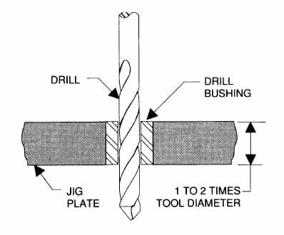 Figure 10-51. Jig-plate thickness should be 1 to 2 times the tool diameter.
Measure Chip Clearance Requirements
Chip clearance is another factor that must be carefully thought out before selecting and installing drill bushings. Chip clearance is the distance between the end of the bushing and the surface to be machined. As a rule, materials or operations that produce large stringy chips normally require greater clearance. Those producing small chips need less clearance.
In most cases, installations with little or no clearance will position the tool more accurately, but have a tendency to clog with chips. Also, when a bushing is positioned against the workpiece, the actual bearing area of the drill in the bushing is reduced by the length of the drill point. Too large a clearance, on the other hand, while less likely to clog, can also increase the chance of positional inaccuracy.
As shown in Figure 10-52, the recommended clearance for general purpose drilling is ½ to 1 ½ times the tool diameter. This clearance between the bushing and workpiece reduces chip interference. An operation such as reaming, which produces smaller chips and requires greater positional accuracy, should generally have a clearance of approximately ¼ to ½ the tool diameter. In these situations, the smaller chips are less of a problem and permit a reduced clearance to ensure the necessary accuracy.
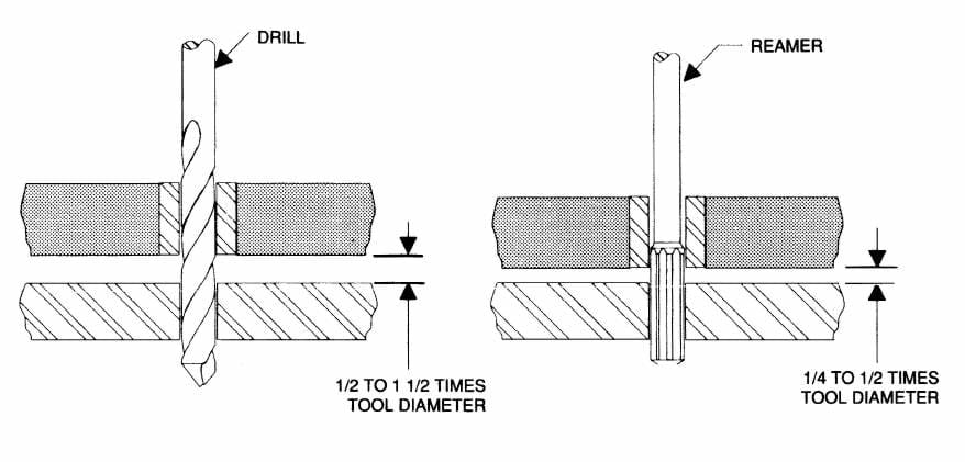 Figure 10-52.
The chip clearance between the bushing and the workpiece should be ½ to 1 ½ times the tool diameter for drilling, and ¼ to ½ times the tool diameter for reaming.
When both drilling and reaming are performed in the same location with a renewable bushing, two different bushing clearances can be used. A bushing arrangement such as shown in Figure 10-53, slip/fixed renewable bushings with two different lengths, meets both clearance requirements. The shorter bushing is used for drilling; the longer bushing is used for reaming.
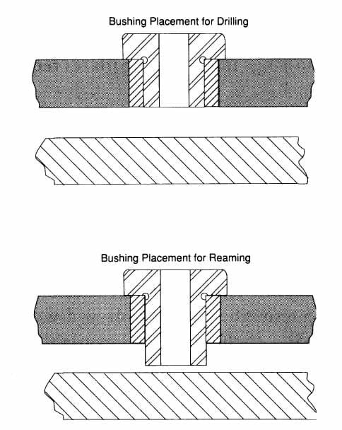 Figure 10-53. When holes are first drilled and then reamed, different length slip-renewable bushings can be used.
Prepare an Installation Hole
The first considerations in drill-bushing installation are the size and geometry of the mounting holes. All mounting holes must be perfectly round. For this reason, the holes should be jig bored or reamed to ensure the correct roundness. Ordinary twist drills should not be used for the finishing mounting holes because they seldom cut a truly round or exact-size hole. The size of the hole is critical if the bushing is to perform properly.
The ideal interference, or press fit, is .0005” - .0008” for liners and headless press-fit bushings, and .0003” - .0005” for head-type press-fit bushings. A greater interference fit can cause problems by either distorting the bushing or deforming the jig plate. Less than the recommended interference fit can result in a loose-fitting bushing that spins when a load is applied.
Other factors to consider in determining the size of a mounting hole are:
- Head-type bushings require less interference to resist drilling thrust.
- Longer bushings in thicker jig plates require less interference.
- Thinwall bushings are more prone to distortion than normal bushings.
- Less-ductile jig-plate materials require less interference.
Utilize the Proper Tools & Procedures for Installation
For drill-bushing installation, an arbor press is preferred, Figure 10-54(a). Using an arbor press permits a constant and even pressure. If an arbor press is unavailable and the bushing diameter is large enough, a drawbolt and washer can also be used, Figure10-54(b). If the only tool available is a hammer, do not strike the bushing directly. This could fracture the bushing. Use a soft-metal punch to cushion the hammer blows.
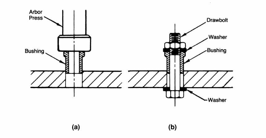 Figure 10-54. Two methods for properly installing press-fit bushings.
To prevent damage to the bushing or mounting hole, coat both the inside surface of the mounting hole and the outside of the bushing with a lubricating compound. This makes the installation easier and reduces any scoring or galling between the mating surfaces. Always install the bushing with the ground lead entering the hole first. This lead helps align and position the bushing for installation.
Use Unground Bushings for Oversized Holes
Each style of press-fit bushing is also available with an unground outside diameter. These are intended for customized applications in mounting holes that are worn or otherwise oversize.
The specific amount of grinding stock left is determined by the size and style of bushing, but ranges from .005” - .020”.
The bushings are specified by adding the letter “U” in the standard bushing designation, e.g. HU-20-16-.1250.
When grinding the bushings to a specific size, a grinding mandrel should be used to ensure the required concentricity of the inside and outside diameters.