Jigs and fixtures are manufacturing tools used to produce identical and interchangeable components. These workholding and tool-guiding devices are essential components in the machining and assembly of parts.
A basic understanding of their construction is necessary to benefit the most from jigs and fixtures.
Jigs and fixtures are identified in one of two ways: by the machine with which they are identified or by their basic construction. A jig, for instance, may be referred to as a "drill jig," but if made from a flat plate, it may also be called a "plate jig." Likewise, a mill fixture made from an angle plate may be called an "angle-plate fixture." To start decoding jig and fixture construction, let's explore different tool bodies that can be used as the base element of all workholders.
Advantages of Jigs and Fixtures
In manufacturing operations, it's essential to meet the higher demands of customers. This means producing quality products as fast and efficiently as possible. Jigs and fixtures help make manufacturing processes more efficient and precise, ensuring all manufacturers can quickly meet their customers' needs.
By utilizing jigs and fixtures in machining processes, manufacturers benefit from:
- Increased Production
- Decreased Manufacturing Costs
- Improved Product Consistency
- Enhanced Assembly Line Safety
- Reduced Non-Productive Hours
- Reasonable Automation Capabilities
- Heightened Versatility and Accuracy
Jigs vs. Fixtures: What's the Difference?
While jigs and fixtures work together in mass-production processes, they are two distinct tools. The two terms are often misused as synonyms, but these two different tools serve different purposes.
A jig controls and guides the cutting tool to work at a predefined location on a workpiece. Fixtures are used to support and locate a workpiece. Fixtures do not guide the tool on a workpiece like a jig.
Jigs are typically lighter than fixtures, requiring additional force to withstand cutting force and vibration. While fixtures require clamping and accessories, a jig can be held or fixed to a table, depending on the application.
Quick Links for Jig & Fixture Tooling:
Types of Jigs and Fixtures
Jig and fixture design is essential for successful machining operations. This section provides a comprehensive guide to understanding the design of jigs and fixtures and how each of these critical workholding devices operates in practice. Carr Lane Mfg. has been a market leader in jig and fixture components for 70 years, offering expert service and high-quality components to enhance machining processes. It's vital to understand the various components involved in the build to design an effective jig and fixture system.
Tool Bodies
The tool body provides the mounting area for all the locators, clamps, supports, and other devices that position and hold the workpiece. The workpiece usually determines a tool body's specific design and construction, the operations to be performed, and the production volume. The three general categories of tool bodies are cast, welded, and built up, as shown in Figure 4-1. Each type of construction can be used for any workpiece. Still, depending on the specific application, one is often a better choice than the others. The first step toward an economical design is to compare the strengths and weaknesses of each tool's body type.
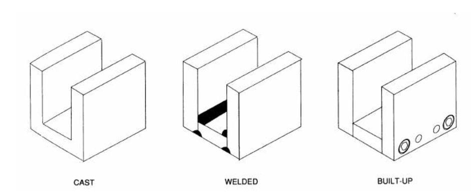
Figure 4.1 The three primary forms of tool-body construction are cast, welded, and built up.
Cast tool bodies are made in a variety of styles and types. The most common casting materials for tool bodies include cast iron, cast aluminum, and cast magnesium. Low melting point alloys and epoxy resins are sometimes used for specialized elements in tool bodies.
Cast tool bodies can have complex and detailed shapes, requiring fewer secondary machining operations and dampening vibration. They are often found in relatively permanent workholders that aren't subject to drastic changes. Cast tool bodies have three significant drawbacks: (1) they are not easily modified for part changes; (2) their fabrication cost is high; (3) they require a lengthy lead time between design and finished tool body.
Welded tool bodies are also made from various materials, often steel or aluminum. Welded tool bodies are inexpensive to build and usually easy to modify, making them more versatile than cast tool bodies. They also require minimal lead time and have high durability and rigidity, providing an excellent strength-to-weight ratio.
Heat distortion is the major drawback of using welded tool bodies. For best results and to ensure the stability of the tool body, welded tool bodies should be stress-relieved before final machining and use. However, this will add to the preparation lead time and cost. Another problem with welded tool bodies is using dissimilar materials. When a steel block, for example, is added to an aluminum tool body, it should be attached with threaded fasteners rather than by welding to the body.
Built-up tool bodies are the most common tool bodies used today. These tool bodies are easy to build and typically require the least lead time between design and finished tool. The built-up tool body is also easy to modify for changes in the part design. Like the welded body, built-up tools are durable and rigid and have an excellent strength-to-weight ratio. Depending on the complexity of the design, the built-up tool body may be the least expensive to construct.
Built-up tool bodies are usually made of individual elements, assembled with screws and dowel pins. They are commonly used for precision machining operations, inspection, and assembly tooling.
Preformed materials can often reduce the cost of machining tool bodies, including precision tooling plates, blocks, risers, cast sections, and angle brackets. Other materials include ground flat stock, drill rods, drill blanks, and structural sections such as steel angles, channels, or beams. Manufacturers can reduce labor costs by using preformed and standard parts when fabricating the workholder.
Tooling plates are standard, commercially available base elements used to construct various workholders. Like other fixturing elements, these plates come in several variations to meet various fixturing requirements.
Rectangular Tooling Plates: Rectangular plates are the most popular of all standard tooling plates. Their rectangular form works well for a wide variety of workholders and comes in various sizes to accommodate many processes. These options range from 12" x 16" to 24" x 32". Rectangular tooling plates are made of ASTM Class 40 gray cast iron, machined flat and parallel.
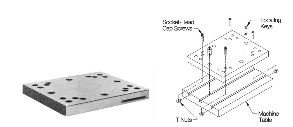
Figure 4-2. Rectangular tooling plates are available in a full range of standard sizes for vertical milling machines.
Round Tooling Plates: Another tooling plate variation is the round tooling plate, as shown in Figure 4-3. Round tooling plates work well on rotary or indexing tables and are available in 400mm, 500mm, and 600mm diameters. They are made of ASTM Class 40 gray cast iron and include a series of mounting holes.
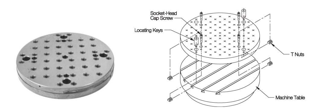
Figure 4-3. Round tooling plates are ideal for rotary or indexing tables.
Square Pallet Tooling Plates: Square pallet tooling plates, Figure 4-4, are another form of tooling plate. The square shape is ideal for palletized arrangements with a necessary square tooling base. Square tooling plates come in five sizes to fit standard machining-center pallets: 320mm, 400mm, 500mm, 630mm, and 800mm. Like the rectangular and round plates, square plates are made of ASTM Class 40 gray cast iron.
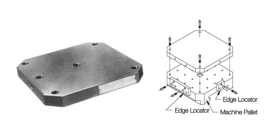
Figure 4-4. Square pallet tooling plates are available for all horizontal machining centers with standard square pallets.
Rectangular Pallet Tooling Plates: This plate type is similar to square pallet tooling plates, except they are made for rectangular machining center pallets in various sizes, including 320 x 400mm, 400 x 500mm, 500 x 630mm, and 630 x 800mm. Figure 4-5 shows how this type can also be mounted on a square pallet by adding a spacer.
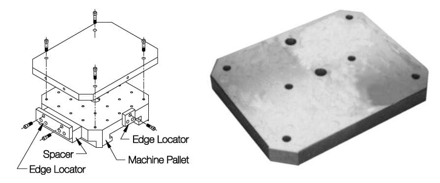
Figure 4-5. Rectangular pallet tooling plates are for machining centers with rectangular or square pallets requiring a larger mounting surface.
Platform Tooling Plates: Platform tooling plates are a variation of the square tooling plates designed explicitly for a mounting surface that is elevated off the machine-tool table. Figure 4-6 shows that the raised mounting surface permits more straightforward access to the workpiece with horizontal machining centers. The added height provides the necessary clearance for the machine-tool spindle, eliminating the dead space between the machine-tool table and the minimum operating height of the spindle.
The added height is also beneficial when machining short parts on a vertical center to avoid Z-axis limit errors. Platform tooling plates come in three sizes, fitting 500mm, 630mm, and 800mm pallets. Platform tooling plates are also made of ASTM Class 45 cast iron.
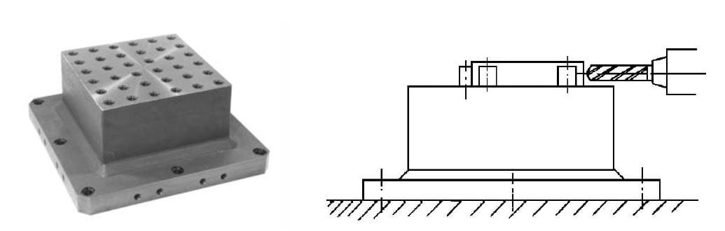
Figure 4-6. Platform tooling plates provide a raised horizontal mounting surface for easier workpiece access on horizontal machining centers.
Angle Tooling Plates: The angle tooling plates, seen in Figure 4-7, are vertical plates that facilitate mounting a large part approximately on the pallet's centerline. These plates are made to fit machining-center pallets that are 400mm, 500mm, 630mm, and 800mm square. Like the other tooling plates we've explored, angle tooling plates are made from ASTM Class 45 cast iron.
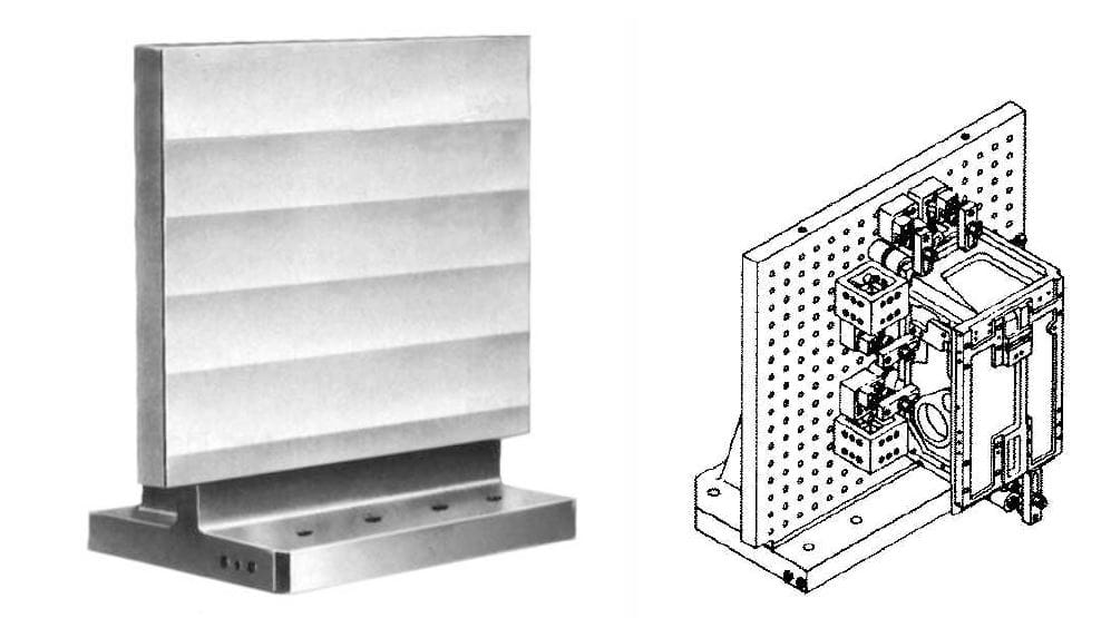
Figure 4-7. Angle tooling plates provide a vertical mounting surface on horizontal machining centers, which is ideal for extensive parts.
Tooling blocks are often used on horizontal machining centers, with the most common types being two-sided or four-sided. These blocks work directly for mounting workpieces or other workholders, ensuring all working faces are accurately finished, machined to tight tolerances and qualified to the base.
Figure 4-8 shows that their dual mounting capability facilitates both JIS mounting (locating from two reference edges) and DIN mounting (locating from the center and radial holes).
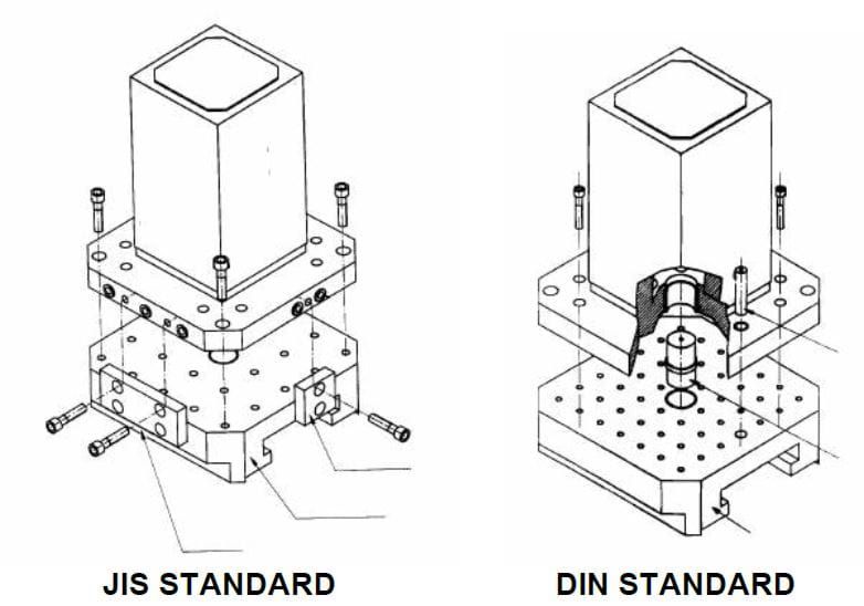
Figure 4-8. Tooling blocks can be located using either two reference edges (JIS standard) or center and radial holes (DIN standard).
Two-Sided Tooling Blocks: The two-sided tooling block, displayed in Figure 4-9, is for mounting workpieces or workholders on two opposite sides. Two-sided tooling blocks work well for fixturing two large workpieces. They come in five pallet sizes to accommodate various machining operations, including 320mm, 400mm, 500mm, 630mm, and 800mm.
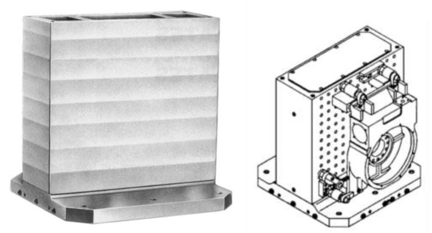
Figure 4-9. Two-sided tooling blocks have two identical wide mounting surfaces for fixturing large parts.
Four-Sided Tooling Blocks: Four-sided tooling blocks mount workpieces or workholders on four identical sides. Because they feature four working surfaces, four-sided tooling blocks are typically chosen to maximize production. These tooling blocks are available in five pallet sizes: 320mm, 400mm, 500mm, 630mm, and 800mm.
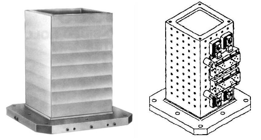
Figure 4-10. Four-sided tooling blocks have four identical mounting surfaces for fixturing medium-size parts.
Precision cast sections are manufactured through precision or investment casting and come in various shapes and sizes. Precision cast sections can be used to create parts that fit together with tight tolerances and align precisely, enhancing the performance, reliability, and longevity of jigs and fixtures.
Most cast sections are available in standard lengths of 25.00", and all sizes and styles are available in precut 6" lengths, with squareness and parallelism within .005"/foot on all working surfaces.
The sections can also be ordered cut to any specified length. The two common cast-section materials are cast iron and cast aluminum. The cast iron sections are made of ASTM Class 40 cast iron with a tensile strength of 40,000 to 45,000 psi. The aluminum sections are 319 aluminum with a tensile strength of 30,000 psi. Cast elements are primarily used for major structural elements of jigs and fixtures rather than as accessory items.
Depending on the workholder design, it is possible to build a complete workholder by combining different sections.
T Sections: as shown in Figure 4-11, T-shaped cast sections are made in two different styles: equal T sections and offset T sections. Equal and offset T sections come in 6.00" lengths or 25.00" lengths. Figure 4-12 shows that the equal and offset T sections have a nearly square cross-sectional profile where width and height are the same. The major difference between the two styles is the position of the vertical member in relation to the horizontal portion. The vertical member of the equal T section is positioned in the middle of the bottom portion.
In contrast, on the offset T section, it is moved to one side. Both styles are available in five sizes ranging from 3.00" x 3.00" to 8.00" x 8.00". The web thickness of these sections is proportional to the overall size, ranging from .63" to 1.25".
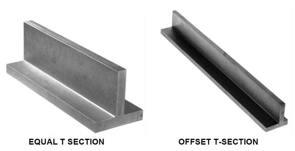
Figure 4-11. T sections are made in two styles: equal T sections and offset T sections.
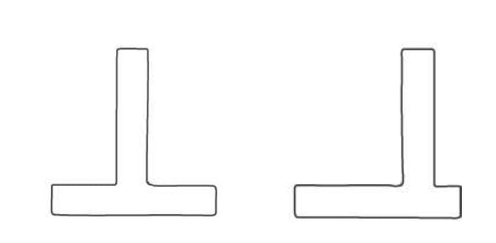
Figure 4-12. The vertical member is positioned in the middle of an equal T section. At the same time, it is moved to one side on an offset T section.
L Sections: The L-shaped cast section, shown in Figure 4-14, has a right-angle shape and is often used for applications when the bottom portion of a T section might get in the way. These cast sections feature identical vertical and horizontal sides and come in five different sizes ranging from 3.00" x 3.00" to 8.00" x 8.00", with available lengths of either 6.00" or 25.00". The web thickness is proportional to the overall size.
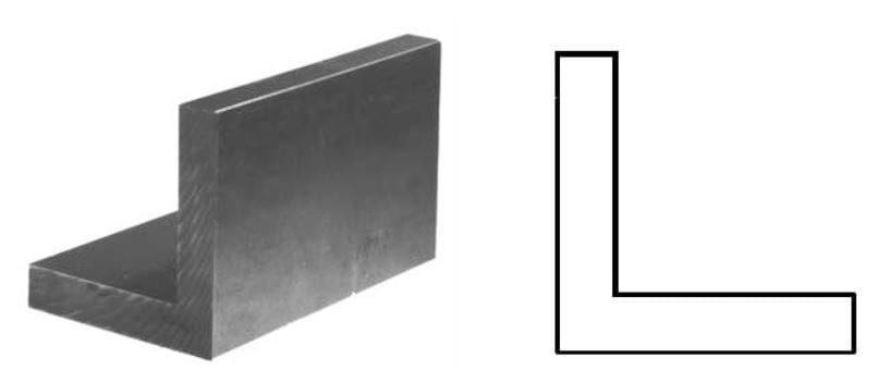
Figure 4-14. The L section features a right-angle shape.
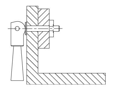
Figure 4-15. A typical fixturing application using an L section.
U Sections: as shown in Figure 4-16, U-shaped cast sections are widely used for channel-type workholders. These sections have a square cross-sectional profile with identical height and width dimensions. U-sections are available in seven sizes ranging from 1.75" square to 8" square.
The web thickness of these sections is, once again, proportional to the overall size. The smaller U sections are made in 19.00" lengths, while the larger sizes are available in full 25.00" lengths. All sizes are available in 6.00" lengths.
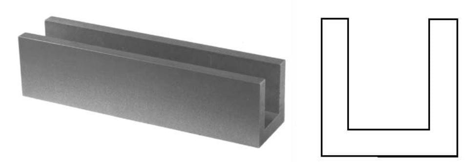
Figure 4-16. The U section features a cross-sectional profile and identical height and width dimensions.
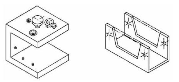
Figure 4-17. Examples of workholders constructed from U sections.
V Sections: V-shaped cast sections are helpful when a V-shaped element is needed for locating or clamping. Thin portions of this material are often used as V pads, while longer lengths are frequently used as V blocks, as shown in Figure 4-19. V sections have a rectangular cross-section with a width greater than the height. The V-shaped groove is machined to 90º ± 10'. V sections come in three sizes, ranging from 1.00" x 2.00" to 2.50" x 4.00" in standard 6.00" and 18.00" lengths.
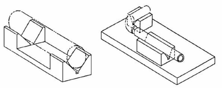
Figure 4-19. V sections are often used as V blocks to locate cylindrical parts.
Square Sections: Square cast sections, shown in Figure 4-20, are typically used as major structural elements. This includes riser elements, supports, or four-sided tooling blocks. Square sections come in four standard sizes, from 3.00" to 8.00" square, with each size available in 6.00" or 25.00" lengths. All external surfaces, except for the ends, are precisely machined.
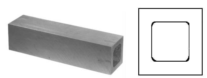
Figure 4-20. The square cast section.
Rectangular Sections: Like square sections, rectangular cast sections are often used as structural elements in workholders. These sections work well for base elements, riser blocks, or similar features. Rectangular sections are available in three standard sizes, from 4.00" x 6.0" to 8.00" x 10.00", and come in 6.00" and 25.00" lengths. Here, too, all external surfaces except the ends are precisely machined.
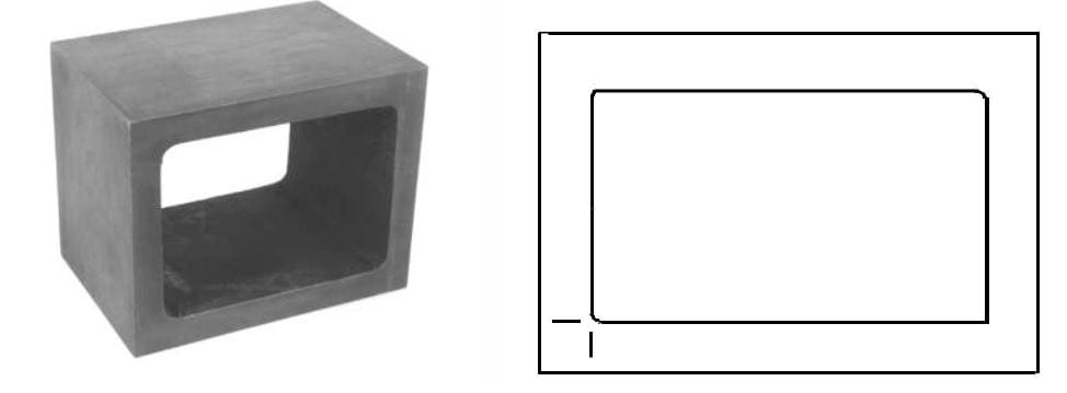
Figure 4-22. The rectangular cast section.
H Sections: H-shaped cast sections, seen in Figure 4-23, are uniquely designed for either complete tool bodies or structural elements, shown in Figure 4-23. These sections are nearly square and come in five sizes ranging from 3.00" x 3.00" to 8.00" x 8.00". All H sections are made at 6.00" and 25.00" lengths.
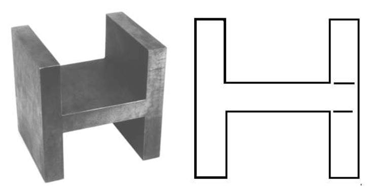
Figure 4-23. The H section.
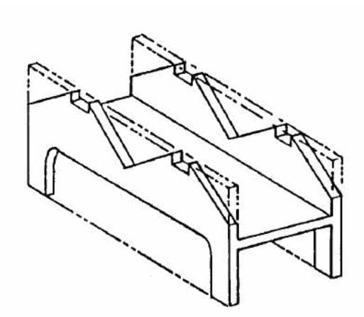
Figure 4-24. An H section is being used as a tool body.
Flat Sections: Flat cast sections are the simplest and most basic type of cast section, commonly used when a cast iron material is preferred over steel flat stock. Flat sections are available in five width and thickness combinations, ranging from .63" x 3.00" to 1.25" x 8.00" and 6.00" and 25.00" lengths. They work well as base elements for smaller jigs or fixtures or structural elements for larger workholders.
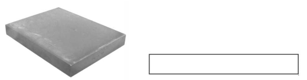
Figure 4-25. The flat cast section.
Angle brackets are fundamental components that support, connect, or mount various parts of a jig or fixture. They are often used when a right-angle alignment or reference is required. Although angle brackets are commonly thought of as 90º elements, adjustable angle brackets and plates are also available.
Plain Angle Brackets: The plain angle bracket, Figure 4-26, is available with or without locating holes. Locating holes can be added for 3-axis accuracy.
Plain angle brackets are typically chosen when a fixed 90º angle is required. The right angle of these plates is closely controlled and is accurate to 90º ± .08º. These brackets are made of ASTM A36 steel or 6061-T6 aluminum, available in 10 different sizes ranging from 2.00" x 2.50" to 6.00" x 6.00", with equal and unequal leg lengths. Plain angle brackets have a web thickness proportional to the overall size, between .22" and .44".
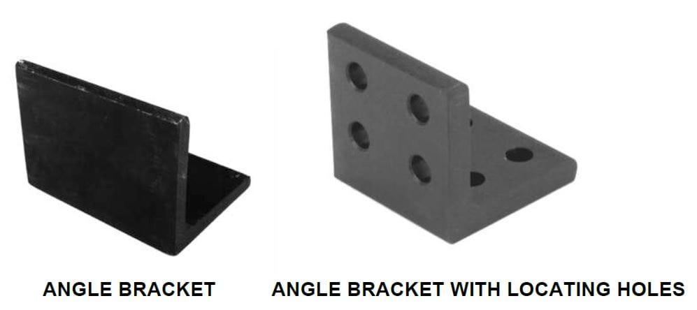
Figure 4-26. Plain angle brackets are machined flat and parallel to close tolerances, available with or without locating holes.
Gusseted Angle Brackets: The gusseted angle bracket, shown in Figure 4-27, is a variation of the standard angle bracket made with a gusset between the horizontal and vertical legs. The gusset stiffens the angle bracket and reduces distortion when applied to heavy loads. These angle brackets also have a right angle accurate to 90º ± .08º and are made of ASTM A36 steel or 6061-T6 aluminum. Gusset angle brackets come in 10 different sizes, ranging from 2.00" x 3.00" to 6.00" x 6.00".
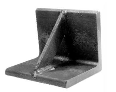
Figure 4-27. Gusseted angle brackets have a gusset for added rigidity and strength.
Adjustable Angle Brackets: Adjustable angle brackets, another variation of the plain angle bracket, are made with a close-tolerance hinge between the horizontal and vertical legs. The hinge pivots the bracket so it may be set at any desired angle. The standard adjustable angle bracket is the plain type, shown at (a), featuring a bolt and nut arrangement for the hinge. The gusseted adjustable angle bracket, shown at (b), also has a bolt and nut hinge. Still, it also has a gusset mount on both legs, allowing the two legs to connect via a gusset that is bolted or welded to the mounts.
The removable pin-type adjustable angle can be used for applications where the angle bracket must be disassembled. This angle bracket, shown at (c), uses an L pin to attach the horizontal and vertical legs.
All adjustable angle brackets are made of 1018 steel. The plain and gusseted adjustable angle brackets come in three sizes ranging from 3.00" x 3.00" to 4.00" x 4.00", with equal or unequal leg lengths. The removable pin type is made in two sizes, 4.00" x 4.00" and 6.00" x 6.00".
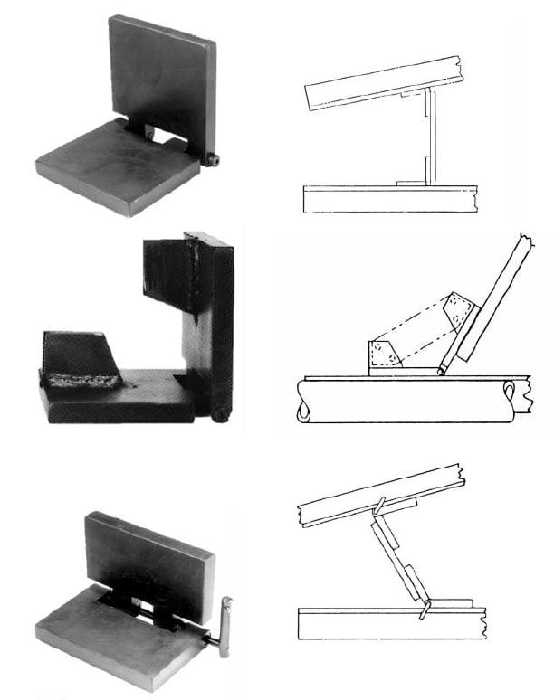
Figure 4-28. Adjustable angle brackets have a close-tolerance hinge for accurate location.
Hoist rings should, for safety reasons, be added to any tool weighing over 30 pounds. When selecting the best hoist rings for your application, consider the following design best practices.
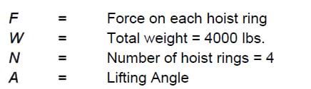
Hoist-Ring Safety Precautions: By following a few basic safety precautions, working with hoist rings can be safe and efficient. The first thing to consider is the load applied to each hoist ring. This is not simply the total weight divided by the number of rings. Using this method, the forces can be significantly greater at shallow lift angles with unevenly distributed loads. Consider the variables below:
- Despite the 5:1 safety factor on hoist rings, never exceed the rated load capacity. This safety margin is needed in case of misuse, which could drastically lower load capacity.
- The tensile strength of fixture-plate material should be above 80,000 psi to achieve a total load rating. Consider through-hole mounting with a nut and washer on the other side for weaker material.
- Do not allow hoist rings to bind. Use a spreader bar, if necessary, to avoid binding.
- Do not use spacers between the hoist ring and the mounting surface.
- Do not apply shock loads. Always lift gradually. Repeat magnaflux testing if shock loading ever occurs.
- Never lift with a hook or other device that could deform the lifting ring. Use only cable designed for lifting.
- Tighten mounting screws to the recommended torque. Because screws can loosen in extended service, periodically check torque. For hoist rings not furnished with screws, mount only with high-quality socket-head cap screws.
- The mounting surface must be flat and smooth for complete contact under the hoist ring. Tapped mounting holes must be perpendicular to the mounting surface.
- After installation, check that the rings rotate and pivot freely in all directions.
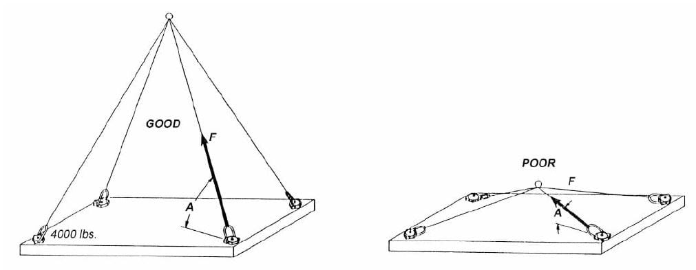
Figure 4-29. The load on a hoist ring is not simply the total weight divided by the number of hoist rings. Shallow lift angles can cause enormous resultant forces.
Standard Hoist Rings: Standard hoist rings, shown in Figure 4-31, have a low profile and are attached directly to the mounting surface with socket-head cap screws. This is the most economical type of hoist ring, available for loads up to 20,000 pounds. The solid forged lifting ring pivots 180º but does not rotate.
Figure 4-31. Standard hoist rings have a forged ring that pivots 180°.
Swivel Hoist Rings: Swivel hoist rings, illustrated in Figure 4-32, have 180º pivot and 360º rotation. These hoist rings, available in the two variations shown, are mounted with a single screw and are always recommended over conventional eye bolts or forged lifting eyes when side loading. The pivot-and-swivel combination permits the hoist ring to accommodate lifting angles that can cause a standard eye bolt or forged lifting eye to break, swiveling rather than staying in a fixed orientation.
Forged lifting eyes and eyebolts have their maximum lifting strength when the axis of the eye is perpendicular to the lifting angle when the lifting eye is screwed to the shoulder. It isn't easy to achieve both of these conditions simultaneously. Still, these challenges can be solved with a swivel hoist ring. These hoist rings are available for loads up to 10,000 lbs in various sizes and finishes, using black oxide or electro-less nickel plate. Many swivel hoist rings are available in stainless steel.
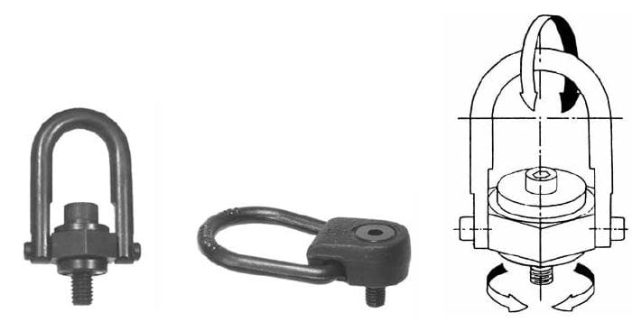
Figure 4-32. Swivel hoist rings pivot 180° and rotate 360° simultaneously to allow lifting from any direction.
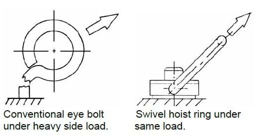
Figure 4-33. Hoist Rings should be used in place of eye bolts for all heavy-lifting applications.
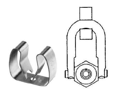
Figure 4-34. Hoist-ring clips keep swivel hoist rings stationary while not in use for lifting.
Other styles of hoist rings are also commercially available. These styles include Heavy-Duty Swivel Hoist Rings, Heavy-Duty Weld Mount Swivel Hoist Rings, and Shackle Hoist Rings, as shown in Figure 4-35.
Heavy-duty swivel Hoist Rings have a forged steel ring, which pivots 180 degrees and swivels 360 degrees simultaneously to allow lifting from any direction. They have a maximum lifting capacity of 30,000 pounds.
Heavy-Duty Weld Mount Swivel Hoist Rings are, as the name implies, attached by welding and are available in capacities up to 24,000 pounds.
Shackle Hoist Rings are designed for permanent mounting on tooling and equipment by being bolted or welded in place.
Each hoist ring can pivot 180 degrees and swivel 360 degrees simultaneously to allow lifting from any direction. They also have a safety factor of 5:1.
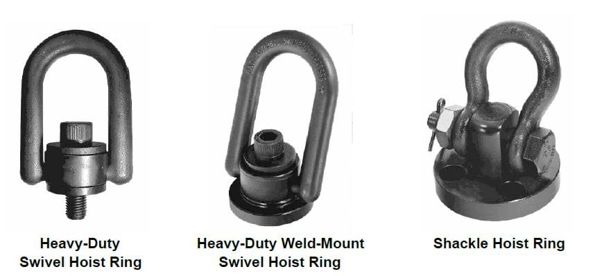
Figure 4-35. Three additional types of swivel hoist rings.
Lifting Pins: Lifting pins, illustrated in Figure 4-36, are a modified form of the hoist ring, featuring a positive-locking four-ball arrangement that holds them in place during lifting. A release button at the opposite end of the pin allows quick installation and removal. Figure 4-37 shows two typical applications. These pins are made of 17-4Ph stainless steel, with sizes available for loads up to 3,400 pounds.
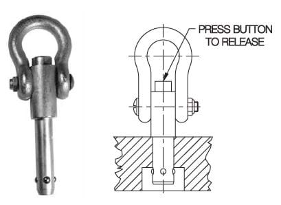
Figure 4-36. Lifting pins are medium-duty hoist rings that can easily be removed entirely
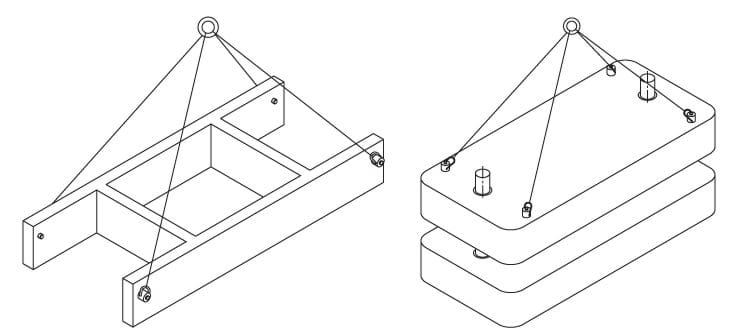
Figure 4-37. Typical applications for lifting pins.
Threaded Inserts
Threaded inserts are widely used to construct and repair workholders, often to reinforce or repair threads. Threaded inserts provide a way to strengthen threaded holes in new workholders where repeated use may cause excessive wear, such as with aluminum or other soft fixture plates. With existing jigs and fixtures, threaded inserts quickly fix stripped, damaged, or worn threads. Two primary forms of threaded inserts are Keenserts and self-tapping threaded inserts.
Keenserts, Figure 4-38, are threaded inserts for repairing and reinforcing applications. The Keensert design uses a standard tap size for installing the insert, eliminating the cost of special taps for threading the mounting holes. As shown, the inserts have unique locking keys that both securely hold the inserts in place and prevent rotational movement. The method of installing these inserts is shown in Figure 4-39.
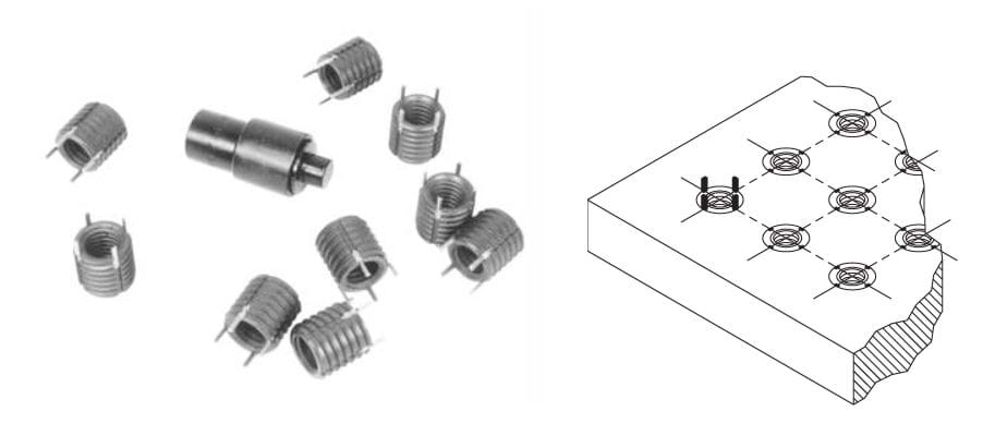
Figure 4-38. Keensert threaded inserts are frequently used to reinforce threads in soft tooling plates.
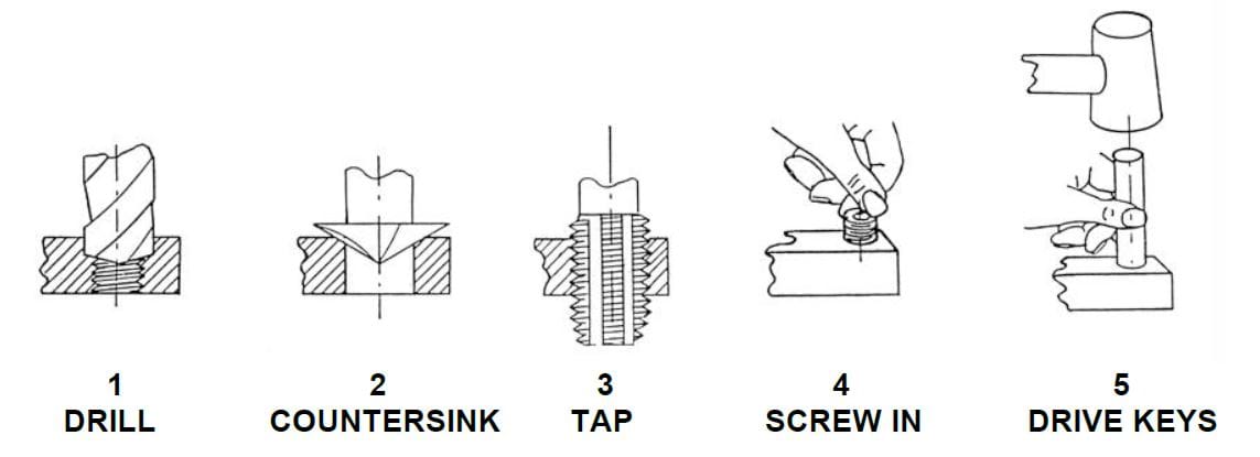
Figure 4-39. Installation steps for Keensert threaded inserts.
- Drill out the old thread if repairing an existing thread or drill a new hole to the specified tap drill diameter (slightly larger than the standard tap drill for that thread size).
- Countersink the entry end of the hole to the specified diameter.
- Tap the new threads to the correct size with a standard tap.
- Screw in the insert until the body is slightly (.010" to .030") below the surface. The locking keys act as a depth stop.
- Drive the keys down with several light hammer taps on the installation tool (or directly on the keys).
Keenserts are made in a variety of forms for almost any application. The inserts are in heavy-duty carbon steel with standard inch sizes from #10 through 1 ½ and metric sizes from M5 to M20. Stainless steel, heavy-duty, and thin-wall inserts are available in plain or internal-thread-locking styles. Various standard Keensert assortments are available for UNC, UNF and metric threads.
One other style of Keensert, ideal for repair work, is the solid Keensert, shown in Figure 4-41. These stainless steel inserts are typically used for relocating tapped or drilled holes and come with external-threaded diameters from 5/16" to 1 3/8".
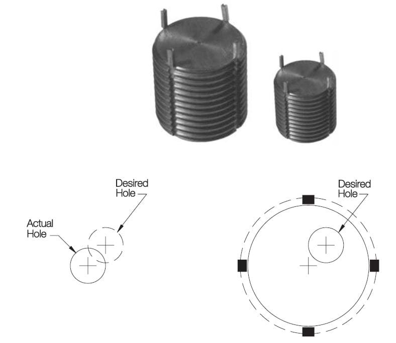
Figure 4-41. Solid Keenserts are handy plugs for relocating misplaced holes.
Fixture Keys
An accurate relationship between the workholder and the machine tool must be established, where fixture keys come into play. Fixture keys establish the initial location and help hold the fixture in place during machining.
The two basic styles of fixture keys are the slot-mounted and hole-mounted types. Slot-mounted fixture keys are made in two variations, the plain fixture key and the step fixture key, illustrated in Figure 4-42. The plain fixture key, shown at (a), is the simplest and least expensive slot-mounted key. These keys are mounted in a slot cut to a depth equal to half the thickness of the key and held in place with a socket-head cap screw.
The second slot-mounted fixture key style is the step key, as shown in (b). These fixture keys are a variation of the standard fixture key. This key's step design allows a fixture with one slot width to work on a machine table with a different slot width. Like the plain-style key, this key is held in place with a socket-head cap screw.
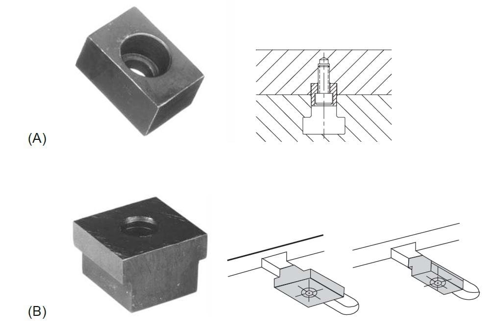
Figure 4-42. Plain fixture keys and step fixture keys.
Hole-mounted fixture keys are also made in several variations. The most popular are the Sure-Lock™ fixture key and the removable locating key, shown in Figure 4-43. Hole-mounted keys eliminate the need to slot fixtures. The Sure-Lock™ fixture key, shown at (a), is the most popular, mounting to any machine-table slot mount in a .6250" reamed hole for interchangeability. This design has a unique locking arrangement to align and lock the fixture key in the hole precisely. As shown, Sure-Lock™ fixture keys can be secured from either the top or bottom of the fixture. These keys are made in many sizes for all standard USA table slots, ranging from 3/8" to 13/16", and metric table slots from 12mm to 22mm.
Locating keys, shown in (b), are the standard removable-type fixture keys for large, heavy fixtures. These keys can be inserted from above after placing the fixture on the machine table and removed if desired after the fixture is fastened. This design keeps the fixture's bottom side free of obstructions. Locating keys all mount in a 1.1875" reamed hole. They are available in many sizes for all standard USA table slots from 9/16" to 7/8" and metric table slots from 14mm to 22mm.
Subplate locating keys, shown in (c), are designed for mounting quick-change fixture plates on a subplate. Round and diamond (relieved) keys are used together to find a precise location without binding. Two standard diameters, .6250" and 1.1875", match standard fixture-key holes, allowing for mounting these same fixture plates on a subplate (3-axis location) or directly on a machine table (2-axis location).
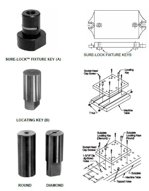
Figure 4-43. Sure-Lock™ fixture keys are ideal for small and medium fixtures, while removable locating keys are best for large, heavy fixtures. Subplate locating keys allow mounting the same fixtures on a subplate with a 3-axis location.
Pallet Fixture Keys: These fixture keys are used for mounting tooling plates and blocks on standard DIN pallets. Each pallet requires one center key and one radial key (for orientation). If desired, the radial key can be removed after fastening the pallet to the machine table. A tapped hole at each pin's top makes insertion and removal easier. Center keys are available for 25, 30, and 50mm holes. Radial keys are available for 20 and 25mm holes.
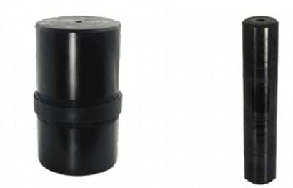
Figure 4-44. Two pallet fixture keys, one for center location and one for radial orientation, are used for DIN mounting on horizontal machining centers.
Jig Construction
Jigs are designed to meet the requirements and specifications of individual workpieces, resulting in an infinite number of different jigs. Even though every jig may differ, each can be grouped into a few categories. The following describes the essential jigs and the best applications for each.
Template Jigs
Template jigs, illustrated in Figure 4-45, are the most straightforward and least expensive jigs. They are generally used for layout or light machining and are designed for accuracy over speed. Template jigs do not have a self-contained clamping device, so if a clamp is needed, a secondary clamp, such as toggle piers, may be used to hold the jig to the workpiece. When a template jig is used for drilling multiple holes, a pin placed in the first drilled hole can reference the jig.
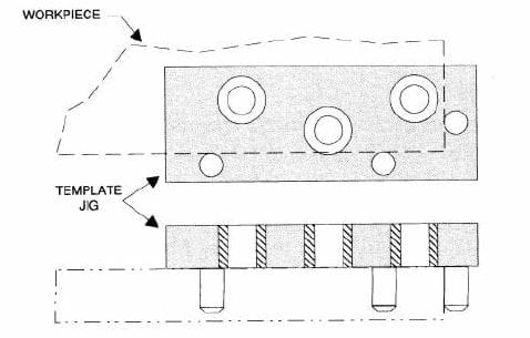
Figure 4-45. Template jigs are simple plates usually held in place by hand.
Plate Jigs
Plate jigs are very similar in their basic construction to template jigs. Figure 4-46 shows that plate jigs have a self-contained clamping device. Although many different clamps can be used, a screw clamp is most commonly paired with these jigs.
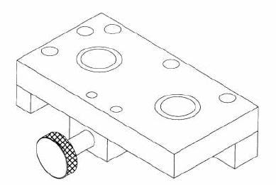
Figure 4-46. Plate jigs are like template jigs, except they include a clamp.
Table Jigs
Table jigs are a variation of the basic template or plate jig, essentially consisting of a template jig installed on legs. Table jigs are designed for applications where the surface to be machined also locates the workpiece. The location is transferred across the underside of the jig plate and down the legs to the machine table. When designing this type of jig, ensure the drilled area is inside the legs to prevent tipping.
Although three legs will work, four are recommended, but it's important to note that four legs will still wobble if a chip is under one leg, while three legs will not. The wobble tells the operator to clear the chips from the locating surfaces.
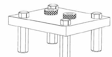
Figure 4-47. Table jigs are like template or plate jigs raised on legs.
Indexing Jigs
Indexing jigs are commonly used for applications where holes must be drilled in a pattern around a center axis. This is done either with an indexing ring holding bushings or by indexing the part itself. With a separate indexing ring, as shown in Figure 4-48, a hand-retractable plunger is frequently used. A ball plunger can also be used for less critical positioning.
The workpiece is the indexing ring, with the first hole drilled and the part rotated to engage the ball plunger. Once located, the part is re-clamped and drilled into a second hole. The indexing is then repeated until all the holes in the part are drilled. The angular position of the ball plunger relative to the drill determines the indexing pattern. So, for four holes, the plunger is located at 90º from the drill, 60º for six holes, 45º for eight holes, and so on.
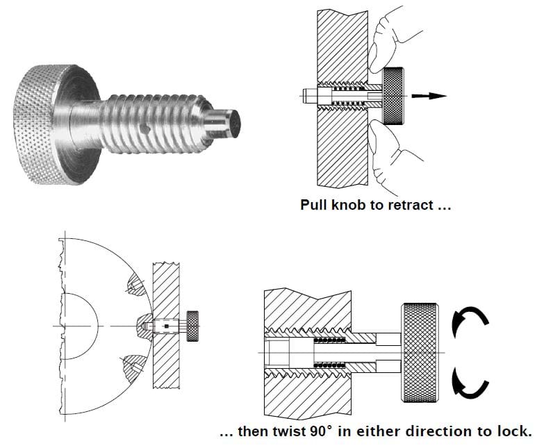
Figure 4-48. A hand-retractable plunger can index a ring holding drill bushing positively.
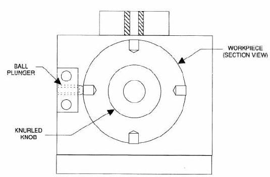
Figure 4-49. A ball plunger can index using holes drilled in the workpiece.
Index Plungers
Index plungers are heavy-duty spring-loaded locators. Index plungers can be engaged or disengaged with a press or pull action. When engaged, the plunger's tip extends into a hole or notch in the workholder to lock parts into a precise position. They are available in a few mounting styles, with either tapered or straight plungers, and can be combined with precision bushings.
Multi-Station Jigs
Multi-station jigs, illustrated in Figure 4-50, are for repetitive, simultaneous operations on several identical parts. In most cases, almost any jig can be used in a multi-station arrangement. As shown, the jigs are mounted and arranged concerning the machining stations. In this example, the jig has four stations: #1 is the load/unload station; #2 is for drilling; #3 is the reaming station; and #4 is where the workpiece is counterbored. An indexing arrangement is also included with this jig to position the jigs at each station accurately.
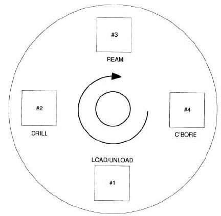
Figure 4-50. Multi-station jigs are used in a continuous, multi-step production process.
Trunnion Jigs
Figure 4-51, Trunnion jigs are for large, heavy, or odd-shaped workpieces. This type of jig rotates the workpiece on precision bearing mounts called trunnions, made in two basic styles: standard and spherical.
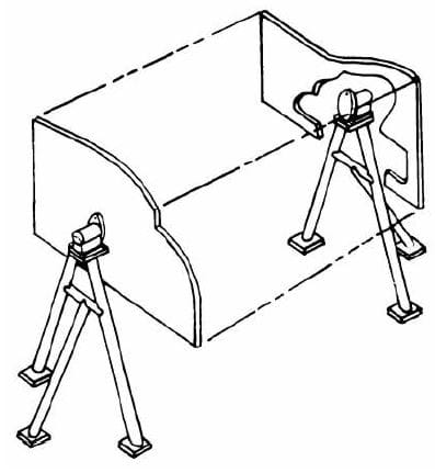
Figure 4-51. Trunnion jigs quickly turn a large part to work on all sides.
Standard trunnions, shown in Figure 4-52, are available in locking or revolving styles. With most trunnion jigs, trunnions are typically used in pairs: the revolving trunnion provides a rotating pivot, and the locking trunnion rotates and locks at any rotational angle. Locking trunnions are secured with a friction-cone arrangement that is engaged by turning the locking handle. Trunnions are intended for low-speed rotation, such as when repositioning a fixture, to allow proper access to complete a weld.
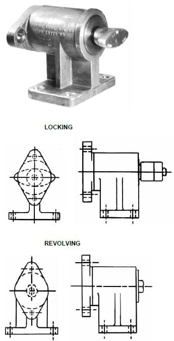
Figure 4-52. Trunnions are usually used in pairs, one locking and one revolving.
These trunnions come in two size ranges: small, with a weight limit of 1,500 pounds at a distance of 18 inches from the face, and large, with a weight limit of 2,500 pounds 18 inches from the face. In pairs, either the weight limit or the distance can be doubled, but not both. For larger fixtures, either longer or heavier, exceeding these limits will lead to premature failure of the trunnion(s).
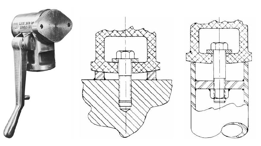
Figure 4-53. Spherical trunnions are ideal for mounting on pipe frames.
Spherical trunnions, shown in Figure 4-53, are a locking trunnions used for pipe frame mounting. The spherical bottom aids in precisely aligning the trunnions, which lock the jig in position by lowering the handle.
Fixture Construction
Fixtures, like jigs, can be grouped into a few categories. These categories are often based on the fixture's construction or the machine it is used with. Common fixture construction methods include:
Plate Fixtures
The plate fixture is the most common. The plate fixture is built with a Carr Lock® Fixture Plate, cast flat section, tooling plate, or similar plate material. All locators, supports, and clamps are mounted directly to the plate. Figure 4-54 shows that a complete plate fixture can be built using standard, off-the-shelf components.
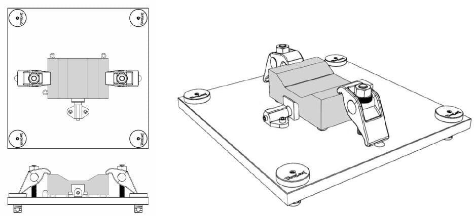
Figure 4-54. Plate fixtures usually hold a workpiece parallel to the machine table.
Angle-Plate Fixtures
Angle-plate fixtures are a variation of the basic plate fixture, often used when the locating surface is at an angle to the machine table. The two main variations of angle-plate fixtures are the right-angle and modified-angle plate fixtures.
Figure 4-55 shows that right-angle plate fixtures are constructed at 90º to the base and can be built with tooling blocks, T-cast sections, L-cast sections, angle brackets, or comparable material. The modified-angle plate fixtures have an angle other than 90º. Adjustable angles or sine plates may be used to build the modified-angle plate fixtures.
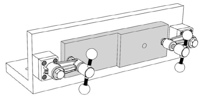
Figure 4-55. Angle-plate fixtures usually hold a workpiece perpendicular to the machine table.
Welding Fixtures
All basic workholding principles should be applied to fixtures used for welding operations. The major differences between most welding and machining fixtures are the locational tolerances and clamping methods. Weight is often a problem with welding fixtures, and in many cases, the fixture is made up of welded sections.
The sections are usually positioned only in the areas where the parts to be joined contact the fixture. Rather than the precision locators found on most machining fixtures, small angle clips, blocks, or similar elements are used as locators.
The clamps for welding fixtures are often toggle clamps. These clamps offer the best combination of design flexibility, holding capacity, and operational speed, and since most toggle clamps move completely clear of the work area when opened, loading and unloading operations are also simplified. Although the clamps may be attached with a screw, toggle clamps are often welded directly to the fixture body.
A few important considerations to keep in mind when building a welding fixture include the following:
- Always construct the fixture so that the parts to be welded can be loaded only in the correct orientation.
- Use supports underneath clamps to prevent distortion.
- Position locators and supports so that any workpiece distortion caused by welding heat loosens, rather than tightens, the workpiece in the fixture.
- Only locate and rigidly clamp essential dimensions and relationships.
- Ensure all areas to be welded are easily accessible.
- When possible, complete welding on a flat, horizontal plane.
- To minimize warping of the workpiece, include provisions to dissipate excess heat in the design.
- Perform as many operations as possible before the workpiece is removed or repositioned.
- Ensure large or heavy loads are entirely supported, and provisions for lifting the jig with a hoist are included.
Lifting Columns
The manipulation of odd-shaped, heavy, or bulky items for welding, inspection, or assembly can lead to operator fatigue, mistakes and injuries. Manual/hydraulic lifting columns can eliminate these conditions while simplifying the performance of these tasks. Available in lifting capacities from 225 to 1,350 pounds, these columns are easily raised or lowered by pumping a foot pedal or releasing pressure to position the workpiece at the ideal level for ease and accuracy.
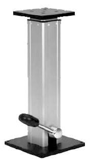
Figure 4-56. Lifting columns are used to raise and lower a fixture quickly.
Rotating modules are also available for these columns to allow workpiece rotation on horizontal or vertical axes. They are available as free rotating modules or with hand or foot pedal locks.
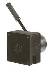
Figure 4-57. Rotating modules allow for easy turning of a large fixture for convenient access.
Inspection Fixtures
Inspection and gaging fixtures are subject to different requirements than machining fixtures, whether inspection is done on a CMM (Coordinate Measuring Machine) or with manual gages. The following are key differences and unique aspects of inspection fixtures:
- The workpiece must be oriented to expose all features to be inspected.
- Machined surfaces are often not used for locating, so they can remain exposed.
- Bridge-type CMMs require different tooling than horizontal-arm machines.
- Since most CMMs can automatically reference a part to the machine, often only approximate orientation in the fixture is required.
- Quick-acting clamps, such as toggle clamps, are widely used in inspection fixtures due to the light clamping forces usually required.
- Inspection fixtures can be either permanent or modular.
Discover the Best Components for Your Jigs & Fixtures with Carr Lane Mfg.
Choosing the right components, tools, and parts for your jig and fixture construction can be lengthy and complex. To discover the best tooling for your application, contact the experts at Carr Lane Mfg. Together, we can ensure you have everything you need to easily complete accurate, repeatable machining processes.