Cad files are provided for all individual items (CLM-4B-BUD, CLM-4MF-BUD, etc.) which can be assembled in cad as needed. Some internal features of the clip buddy assembly (springs, internal components, etc…) are not included in cad for clarity and reduced complexity. Cad files include levers and optional mounting brackets in all potential orientations. Unused orientations can be deleted as desired. All options and accessories include fasteners to attach the item to the Clip Buddy body. Fasteners for attaching to a fixture are not included. Optional levers and mounting brackets are shipped pre-assembled whenever possible.
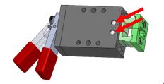
Holes in the Clip Buddy body are as follows:
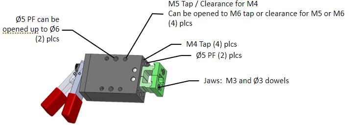
All optional mounting brackets have M5 tapped holes and Ø5 PF dowel holes for mounting to the fixture Jaw end piece anvils are constructed from 1045 unhardened steel, except for “xxxxSS” versions which have SS420 end pieces. The main body is 1045 steel. Other components are 1045 steel or die-cast metal. When using the cable remote actuation option, order one CLM-4CBL-BUD or CLM-4CBL2-BUD (or CLM-4CBL-3M-BUD/CLM-4CBL2-3M-BUD) for each Clip Buddy to be cable actuated. CLM-4CBL-BUD and CLM-4CBL2-BUD include cable adapter items pre-installed to the back end of the Clip Buddy and a separate 2-meter cable assembly (3 meters for CLM-4CBL-3M-BUD/CLM-4CBL2-3M-BUD) which connects to the CLM-RA12-BUD actuator box. Also, order CLM-RA12-BUD unit(s) as needed. Each CLM-RA12-BUD will actuate 1-12 Clip Buddy units that have a cable option. When using the CLM-4CYL-BUD pneumatic option, air pressure can be provided by one of 2 methods. 1) Pneumatic actuators can be used: CLM-PA6-BUD for 1-6 units, and CLM-PA10-BUD for 1-10 units. 2) Shop air with CLM-RV-BUD regulator and valve can be used. There is a separate information document for pneumatic actuation.
Position the Clip Buddy body as close as possible to the feature mating surfaces to provide rigidity.
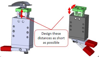
For tight-clearance applications, consider fabricated inside-mounted jaw end pieces with CLM-5X-BUD as shown as one option.

In general, it is suggested to use Clip Buddy versions with jaw end pieces included (CLM-3B-BUD, CLM-4A-BUD, CLM-4B-BUD, CLM-5B-BUD, CLM-5C-BUD) whenever possible to avoid the need to fabricate, attach, and adjust jaw end pieces.
For situations where custom jaw end pieces are necessary (CLM-3L-BUD, CLM-3X-BUD, CLM-4X-BUD, CLM-5L-BUD, CLM-5X-BUD), it is recommended to plan for grinding the top faces and possibly the side surfaces of the jaw end pieces after assembly to ensure flatness, squareness, and matched surfaces. When installing custom jaw end pieces that are designed to contact each other, it is critical that the jaw end pieces make contact at the same time that the jaw arms naturally close. If the jaw end pieces prevent the jaw arms from closing to their natural closed position, there may be jaw motion in the closed assembly.
When custom jaw end pieces are required, consider using designs wherein the jaw end pieces do not contact each other, but have a small gap. This will eliminate the need to fine-tune the closing of the jaw end pieces to match the internal jaw-closing positions.
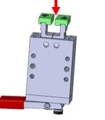
For machining assembled units, it is recommended to align to 2 side dowel holes and clamp the jaws across the sides for all versions, with or without jaw end pieces. 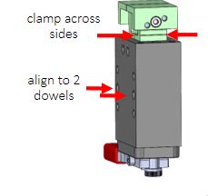
If disassembly is necessary, mark the jaw locations relative to the block. Then carefully punch out (2) dowels Ø5 taking care not to scrape the sides of the holes. Then slide the 2 jaws together with the small spring between them out of the front of the block. To reassemble, reverse the steps making sure to reinstall all components in the original positions and orientations. Hold the lever open during reassembly.
Patent 10,072,685