
The Carr Lock System allows accurately locating and clamping at the same time, with just the turn of a hex wrench. Ideal for mounting quick-change tooling on a subplate. Each mount consists of three components: (1) a Carr Lock Clamp with a precisely ground shank; (2) a Liner Bushing in the top plate; (3) a Receiver Bushing in the subplate. This compact assembly provides considerable holddown force, together with an incredible ±.013mm repeatability.
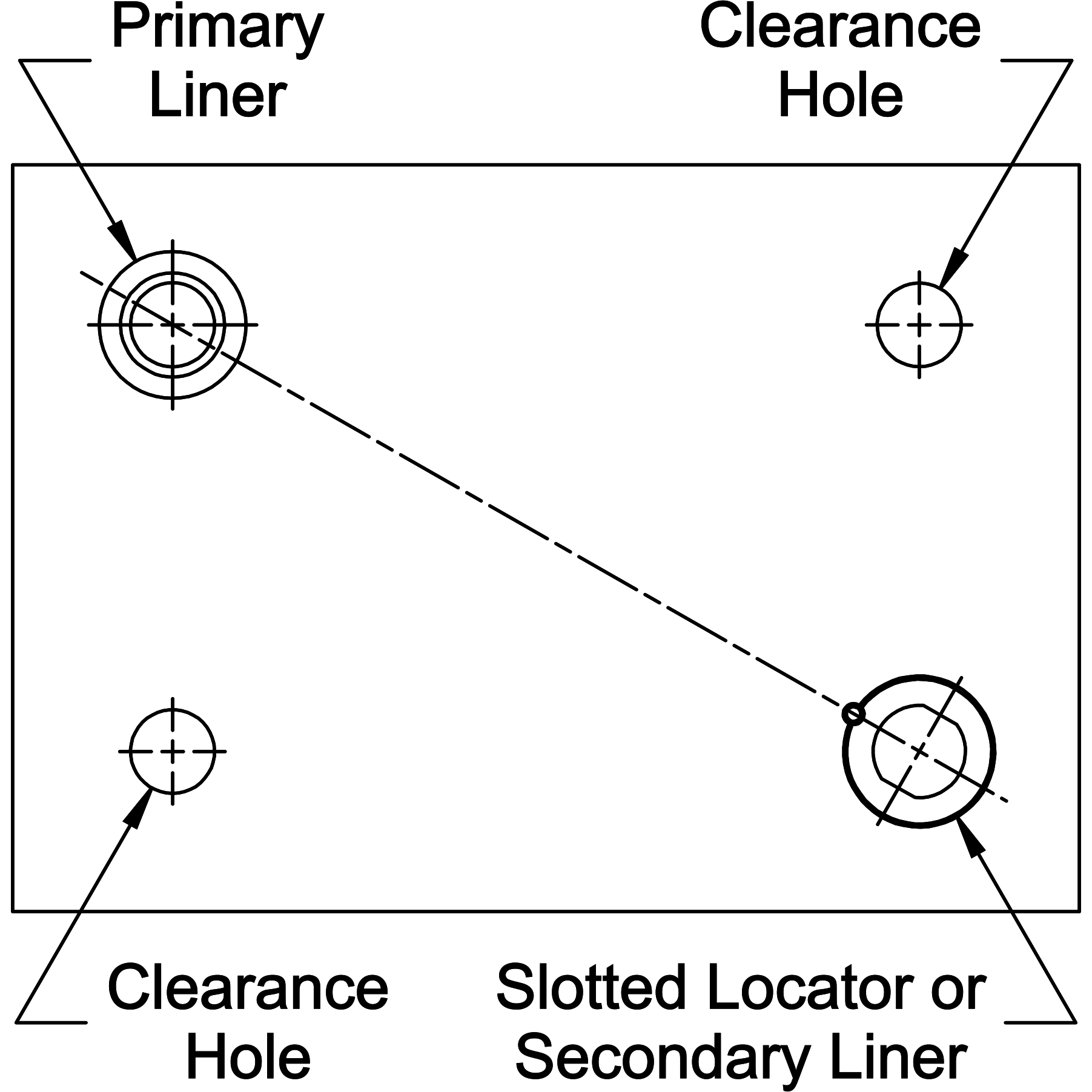
Each top plate should have one Carr Lock Mount designated as its primary reference point, and one as its secondary reference point. These two mounts should be as far apart as possible. The secondary reference point should have a relieved liner to avoid redundant location (binding). Additional Carr Lock Mounts can be used for more clamping force, but these should be installed in clearance holes, not locating liners. Note that the same Carr Lock Clamp fits any type of liner or a clearance hole. To mount top plates with more than two Carr Lock Clamps, use clearance holes .38-.76mm over nominal size for the additional holes, instead of liner bushings, to avoid redundant location. (Still use four Receiver Bushings in the subplate.)

Plate thickness must be ±.13mm to achieve proper clamping force. Extra-thick top plates can be counterbored to achieve proper clamping thickness (hold thickness to ±.13mm). Special-length Carr Lock Clamps are also available, as specials.