Locating and clamping play pivotal roles in any workholding system. Accurate positioning of the workpiece is crucial for precision machining. Carr Lane Mfg. delves into the essential principles of locating and clamping, offering valuable insights into achieving precise and consistent results.
Basic Principles of Locating
Workholders must position the workpiece accurately and consistently relative to the cutting tool. Using locators correctly is vital for this purpose. These tools ensure proper referencing of the workpiece, making the process repeatable and successful.
Referencing and Repeatability
Referencing involves positioning the workpiece relative to the workholder and the cutting tool through guiding devices. Achieving accurate placement within the workholder is crucial for machining precision.
Designing a workholder requires considering the referencing of both the workpiece and the cutter to ensure accurate machining.
Repeatability, the workholder’s ability to consistently produce parts within tolerance, relies on precise referencing capabilities. The ideal locating point is a machined surface for consistency.
“Referencing“ is a dual process of positioning the workpiece relative to the workholder and the workholder relative to the cutting tool. This process is performed by guiding or setting devices.
With drill jigs, referencing uses drill bushings. With fixtures, referencing uses fixture keys, feeler gages, or probes. On the other hand, referencing the workpiece to the workholder is done with locators.
The Mechanics of Locating
A workpiece has twelve degrees of freedom that must be restricted for proper referencing. Sturdy enough to resist cutting forces, Locators play a crucial role by providing a positive stop for the workpiece, ensuring accurate machining.
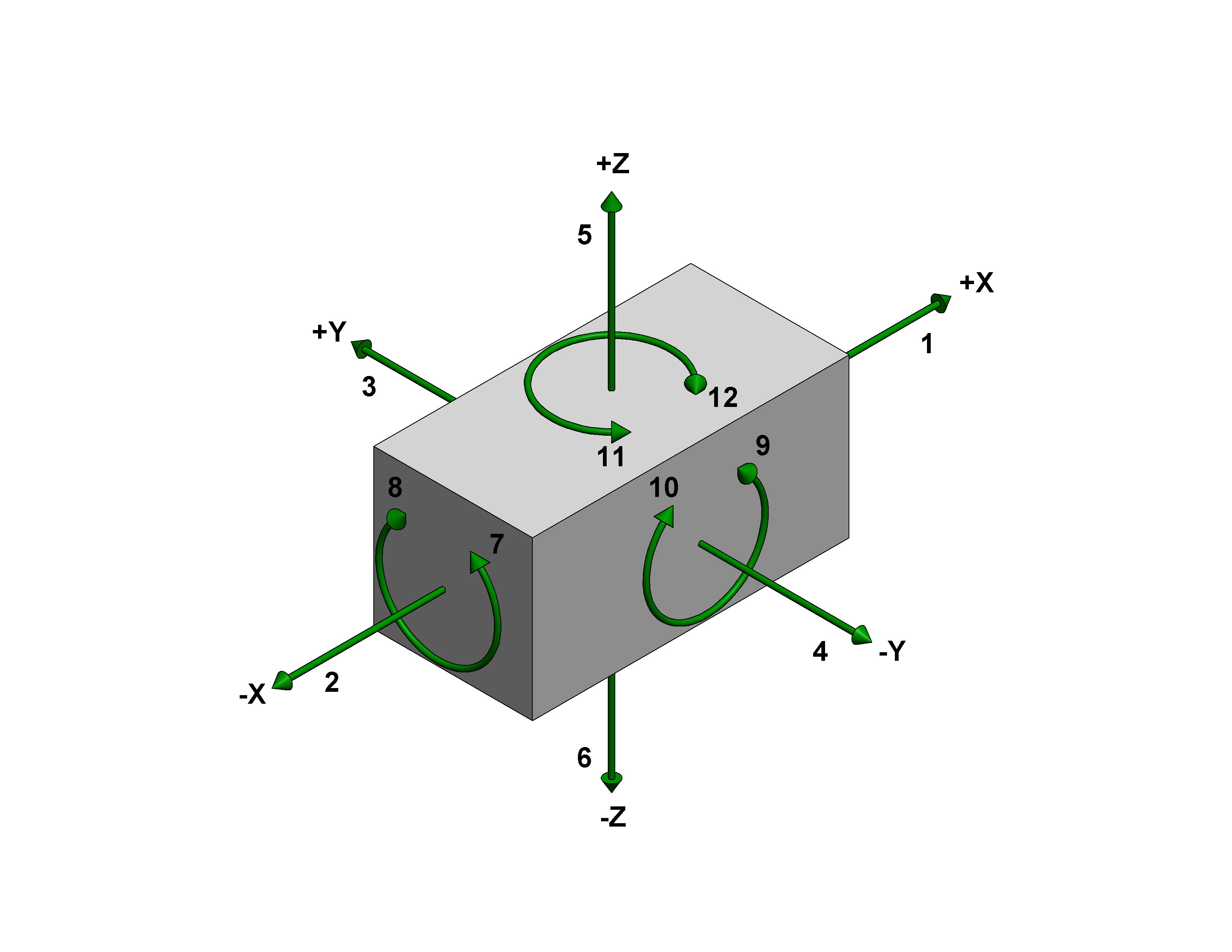
As shown in Figure 3-1, the twelve degrees of freedom all relate to the central axes of the workpiece, including six axial degrees of freedom and six radial degrees of freedom.
The axial degrees of freedom permit straight-line movement in both directions along the three principal axes, shown as x, y, and z. The radial degrees of freedom permit rotational movement around the same three axes in both clockwise and counterclockwise radial directions.
![]()
Figure 3-1. The twelve degrees of freedom.
Forms of Location
We categorize location into three forms: plane, concentric, and radial. Each form has its specific application, with plane locators working from any surface, concentric locators focusing on a central axis, and radial locators restricting movement around a central point.
In most applications, plane-locating devices locate a part by its external surfaces, as shown in Figure 3-2a.
Concentric locators primarily locate a workpiece from a central axis, though this axis may or may not be in the center of the workpiece. The most common type of concentric location is a locating pin placed in a hole.
Some workpieces, however, might have a cylindrical projection that requires a locating hole in the fixture, as shown in Figure 3-2b.
The third type of location is radial, and as seen in Figure 3-2c, the radial locators restrict the movement of a workpiece. In many cases, locating is performed by combining these three locational methods.
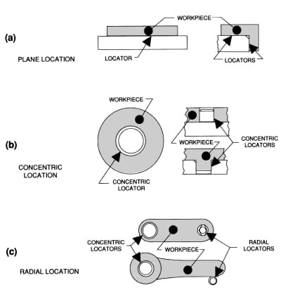
Figure 3-2. The three forms of location are plane, concentric, and radial.
Locating from External Surfaces
Locating from flat surfaces uses solid, adjustable, and equalizing supports to position the workpiece accurately. The 3-2-1 locational method is a common approach, using six locators to reference and restrict the workpiece’s movement effectively.
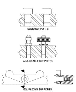
Figure 3-3. Solid, adjustable, and equalizing supports locate a workpiece from a flat surface.
Solid Supports are fixed-height locators that precisely locate a surface in one axis. Though solid supports may be machined directly into a tool body, a more economical method can be accomplished with installed supports such as rest buttons.
Adjustable supports are variable-height locators. Like solid supports, they will also precisely locate a surface on one axis. These supports are used where workpiece variations require adjustable support to suit different heights and are mainly used for cast or forged workpieces with uneven or irregular mounting surfaces.
Equalizing supports are a form of adjustable support used when compensating support is required.
Although these supports can be fixed in position, equalizing supports typically float to accommodate workpiece variations. As one side of the equalizing support is depressed, the other raises the same amount to maintain part contact.
Figures 3-4 show three locators, or supports, placed under the workpiece. The three locators are usually positioned on the primary locating surface. This positioning restricts axial movement downward, along the z-axis (#6) and radially about the x (#7 and #8) and y (#9 and #10) axes. Together, the three locators restrict five degrees of freedom.
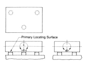
Figure 3-4. Three supports on the primary locating surface restrict five degrees of freedom.
The following two locators are usually placed on the secondary locating surface, as shown in Figures 3-5. They restrict an additional three degrees of freedom by arresting the axial movement along the +y axis (#3) and the radial movement about the z (#11 and #12) axis.
Two additional locators are placed on the secondary locating surface, as shown in Figure 3-5, to restrict an additional three degrees of freedom by arresting the axial movement along the +y axis (#3) and the radial movement about the z (#11 and #12) axis.
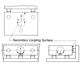
Figure 3-5. Adding two locators on a side restricts eight degrees of freedom.
The final locator, shown in Figure 3-6, is positioned at the end of the part, restricting axial movement in one direction along the –x-axis. Together, these six locators restrict nine degrees of freedom. The remaining three degrees of freedom (#1, #4, and #5) will be restricted by clamps.
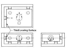
Figure 3-6. Adding a final locator to another side restricts nine degrees of freedom, completing the 3-2-1 location.
Locating from Internal Surfaces
Locating from an internal diameter is efficient, using locating pins and plugs based on the feature’s maximum material condition (MMC). This method ensures accurate positioning by restricting movement in specific directions.
The two forms of locators used for internal location are locating pins and locating plugs. The only difference between these locators is their size: locating pins are used for smaller holes, and locating plugs are used for larger holes.
Figure 3-7 shows that the plate under the workpiece restricts one degree of freedom, preventing any axial movement downward along the -z (#6) axis. The center pin, acting in conjunction with the plate as a concentric locator, prevents any axial or radial movement along or about the x (#1, #2, #7, and #8) and y (#3, #4, #9, and #10) axes.
Together, these two locators restrict nine degrees of freedom. The final locator, the pin in the outer hole, is the radial locator that restricts two additional degrees of freedom by arresting the radial movement around the z (#11 and #12) axis. Together, the locators restrict eleven degrees of freedom. The last degree of freedom, in the +z direction, will be restricted with a clamp.
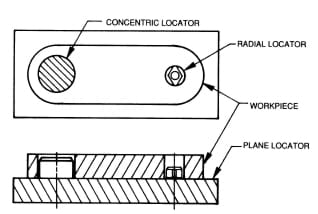
Figure 3-7. Two mounted on a plate restrict eleven out of twelve degrees of freedom.
Analyzing Machining Forces
Understanding the direction and magnitude of machining forces is essential for fixture layout. Analyzing these forces helps design workholders that properly direct cutting forces and ensure precise machining.
In Figure 3-8, the milling forces push the workpiece toward the solid jaw when clamped adequately in a vise. The clamping action of the movable jaw holds the workpiece against the solid jaw. It maintains the position of the part during the cut.
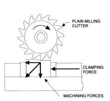
Figure 3-8. Cutting forces in a milling operation should be directed into the solid jaw and base of the vise.
As shown in Figure 3-9, cutting forces push the workpiece down against the supports in the drilling process. There’s also a force that pushes sideways against the drill, which helps keep the workpiece in place against the locators. The clamps are there to make sure the workpiece stays put during drilling. The most significant impact happens when the drill exits the other side of the workpiece. If the workholder is designed right, these forces help keep the workpiece stable for accurate drilling.
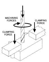
Figure 3-9. The primary cutting forces in a drilling operation are directed downward and radially about the axis of the drill.
When designing fixtures, predicting the strength and direction of cutting forces on the workpiece is critical. This prediction can be an educated guess from experience or a data calculation. A basic formula, seen in Figure 3-10, helps determine the force based on how the cutting tool interacts with the workpiece.
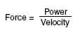
Please note: “heaviest-cut horsepower“ is not total machine horsepower but the maximum horsepower used during the machining cycle. Typical machine efficiency is roughly 75% (.75). The number 33,000 is a units-conversion factor.
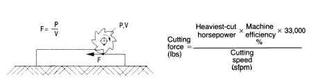
Figure 3-10. A simple formula to estimate the magnitude of cutting forces on the workpiece.
The above formula only calculates force magnitude, not direction. Cutting force can have x-, y-, or z-axis components. Force direction (and magnitude) can vary drastically from the cut’s beginning, middle, and end. Figure 3-11 shows a typical calculation. Intuitively, force direction is virtually all horizontal in this example (negligible z-axis component). Still, the direction varies between the x and y axes as the cut progresses.
Figure 3-11. Example of a cutting force calculation.
Locating Guidelines
The main job of a locator is to reference the workpiece and guarantee consistent results. To do this effectively, correctly positioning locators is crucial. Here are the key points to remember:
Always try to place locators on the machined surface of the workpiece. Machined surfaces ensure consistent and stable positioning.
Depending on the workpiece, you might use the entire machined surface or specific areas. Machined holes are particularly effective for positioning since they require fewer locators and provide the most accurate location.
Another reliable setup uses two machined surfaces that form a right angle, ideal for the six-point location method. The most crucial factor in choosing a surface for location is its ability to provide consistent results.
Spacing between locators is critical for accuracy. You should place locators as far apart as possible to avoid inaccuracies and ensure stability. Figure 3-12 shows two workpieces positioned using the six-point method, highlighting the importance of locator spacing. The piece shown in part (b) has locators too close to each other, leading to poor positioning. In contrast, part (a) shows locators well-spaced, achieving accurate placement. Wide spacing helps compensate for any irregularities in the locators or the workpiece, ensuring maximum stability.
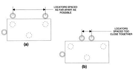
Figure 3-12. Locators should be spaced as far apart as practical to compensate for slight irregularities and to achieve maximum stability.
Figure 3-13 illustrates issues arising from placing locators near each other. When the center positions of the locators are off by just .001 “, the impact on the part’s location can vary significantly based on their spacing. In the scenario depicted in (a), this slight misalignment barely affects the part’s position due to adequate spacing between the locators.
However, when locators are positioned as closely as shown in (b), even a minor .001 “ difference can significantly impact the accuracy of the part’s location. Another challenge is when locators are positioned too closely, as demonstrated in (c). This close spacing can cause the part to wobble on the locators within the workholder, leading to instability and inaccurate machining.
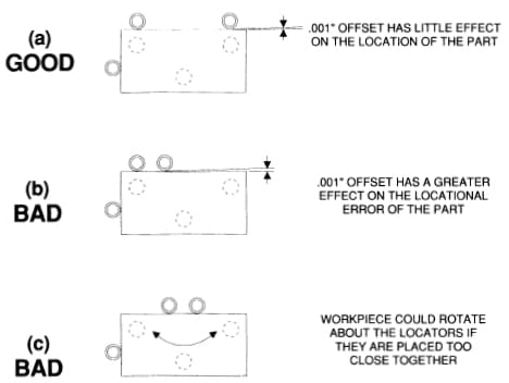
Figure 3-13. Positioning locators too close together will affect the locational accuracy.
Controlling Chips
When placing locators, the last thing to consider is dealing with chips, which are always part of machining. Keeping chips from messing up how the workpiece fits in the holder is essential.
You can manage chips by placing locators without many chips or making locators that lessen chip impact. If neither is possible, use locators designed to be easy to clean, or that can keep chips away by themselves. Figures 3-14 shows different strategies for making locators less affected by chips.
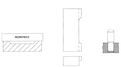
Figure 3-14. Locators should be relieved to reduce locational problems caused by chips.
Coolant build-up can also cause problems with machining accuracy and location. Solve this problem by drilling holes or milling slots in areas of the workholder where the coolant is most likely to build up. With some workholders, coolant-drain areas can also act as a removal point for accumulated chips.
When designing a workholder, always try to minimize the chip problem by removing areas of the tool where chips can build up. Omit areas such as inside corners, unrelieved pins, or similar features from the design. Chip control must be addressed in the design of any jig or fixture to achieve stable and accurate machining.
Avoiding Redundant Location
When creating a workholder, it’s important to avoid using redundant locators, which means not using multiple locators to control the same movement. Doing this can cause problems with the part's position, affect the machining accuracy, and lower overall efficiency. It can also lead to damage from too much pressure on the part or the fixture itself.
Figures 3-15 gives examples of this. Part (a) shows that using two locators on flat surfaces that do the same job isn’t necessary. Because parts vary slightly in size, they will unlikely touch both locators simultaneously.
Part (b) highlights a similar issue with using two locators around a circle – you should only need one.
Part (c) illustrates the problem of using both hole and edge locators simultaneously, which can cause confusion and make it hard to place or remove parts properly.
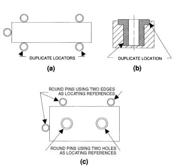
Figure 3-15. Examples of redundant location.
A general rule of thumb is always to avoid redundant location. The simplest way to eliminate it is to check the shop print to find which workpiece feature is the reference feature.
How a part is dimensioned often indicates which surfaces or features are essential. As shown in Figure 3-16, since the part on the left is dimensioned in both directions from the underside of the flange, use this surface to position the part. However, the part shown to the right is dimensioned from the bottom of the small diameter. This is the surface that should be used to locate the part.
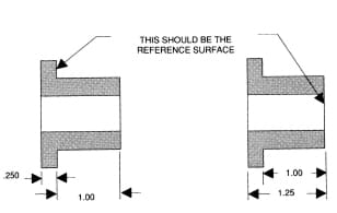
Figure 3-16. The best locating surfaces are often determined by how the part is dimensioned.
Preventing Improper Loading
Foolproofing prevents improper loading of a workpiece, which is more prevalent with symmetrical or concentrated parts. The simplest way to foolproof a workholder is to position one or two pins in a location that ensures correct orientation, as shown in Figure 3-17. With some workpieces, however, you must take more creative approaches to foolproofing to ensure the workpiece can be loaded correctly.
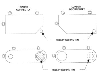
Figure 3-17. Foolproofing the location prevents improper workpiece loading.
Figure 3-18 shows ways to foolproof part location. In the first example, shown at (a), an otherwise –non-functional foolproofing pin ensures proper orientation. This pin would interfere with one of the tabs if the part were loaded any other way, ensuring it is loaded correctly.
In the following example, shown in (b), a cavity in the workpiece prevents the part from being loaded upside-down. Here, a block slightly smaller than the opening of the part cavity is added to the workholder. An adequately loaded part fits over the block, but the block keeps an improperly loaded part from entering the workholder.
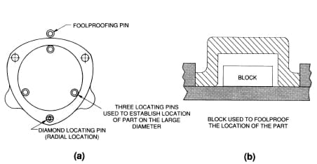
Figure 3-18. Simple pins or blocks are often used to foolproof the location.
Using Spring-Loaded Locators
One method to help ensure the accurate location is the installation of spring-loaded buttons or pins in the workholder, as seen in Figure 3-19. These devices are positioned so their spring force pushes the workpiece against the fixed locators until clamped, ensuring repeatable locating and streamlining the clamping process.
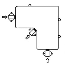
Figure 3-19. Spring-loaded locators help ensure the correct location by pushing the workpiece against the fixed locators.
Determining Locator Size and Tolerances
To choose the right locator size, look at the workpiece’s features. Use the Maximum-Material Condition (MMC) principle, which is the thickest part of an external or the smallest part of an internal feature. For instance, if a hole’s diameter can be between .500 and .510 inches, aim for the smallest size (.500 inches) to ensure the locator fits well.
Make the locator a bit smaller to fit comfortably. If a hole is .500 inches at MMC, a locator pin might be .4995 inches for a slight gap, ensuring it’s neither too tight nor too loose. Figures 3-20 and 3-21 provide examples of applying MMC to both types of features and selecting locator sizes.
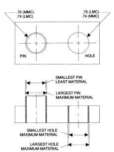
Figure 3-20. Locator sizes are always based on the workpiece features' maximum material condition (MMC).
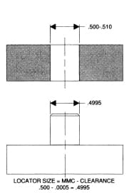
Figure 3-21. Determining the size of a single locating pin based on maximum-material conditions.
The accuracy of a workholder needs to be higher than that of the workpiece. There are two main tolerances for locators: one for the locator’s size and another for its position. Different methods can set these tolerances, sometimes based on engineering decisions or specific measurements related to the part.
Making tolerances tighter increases production costs significantly. For example, making a tolerance twice as strict could quintuple the cost. The ability to achieve these tolerances, or manufacturability, is also crucial. Depending on how strict the tolerance is, the method to create a hole, for instance, can range from punching to drilling, reaming, and even lapping for the most precise measurements.
It’s important to remember that not all tolerances can be met by every toolroom; some are too precise to achieve in practice. Not every part of a workholder needs the same level of tolerance. Some parts can have looser tolerances without affecting the overall function.
Using percentage-based tolerances can help maintain a balanced relationship between the workpiece and workholder tolerances. Setting workholder tolerances as a percentage of the workpiece tolerances ensures consistency.
Typically, these percentages range from 20% to 50% of the workpiece’s tolerances, as determined by engineering standards. This approach ensures that tolerances are proportional and manageable.
Guidelines
Locating the workpiece is the primary function of a jig or fixture. Once located, the workpiece must also be held to prevent movement during the operational cycle. The process of holding the position of the workpiece in the jig or fixture is called clamping. The primary devices used for holding a workpiece are clamps. Careful selection of the clamping devices and their location is essential for proper performance.
Factors in Selecting Clamps
Selecting the proper clamps for a job involves understanding their two leading roles: keeping the workpiece in place against the locators and stopping it from moving. Locators are designed to handle the main cutting forces during machining, not the clamps.
Holding the Workpiece Against Locators
Clamps focus on keeping the workpiece steady and dealing with any forces that try to move it when cutting tools exit the material.
For instance, the drill’s main forces push down and sideways when drilling, but as the drill comes out on the other side, it can lift the workpiece. Clamps must be strong enough to prevent this movement without having to counteract the main drilling forces.
A milling machine vise shows how locators and clamps work together. The vise’s solid parts act as locators, absorbing the cutting forces, while the movable part is the clamp, securing the workpiece in place. This setup ensures machining accuracy by keeping the workpiece stable and correctly positioned throughout the operation.
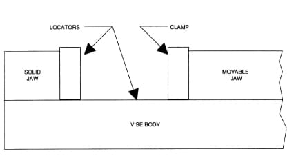
Figure 3-22. A vise contains both locating and clamping elements.
Holding Securely Under Vibration, Loading, and Stress
Consider the vibrations, stress, and forces they’ll face when choosing clamps. Clamps need to keep the workpiece steady without loosening during operation. Adding a safety margin to the forces helps ensure stability.
Preventing Damage to the Workpiece
It’s crucial to pick clamps that won’t damage the workpiece. Too much force can bend or mark it. Use clamps with rotating pads or softer materials to avoid damage and ensure they’re strong enough without causing harm.
Improving Load/Unload Speed
The efficiency of loading and unloading the workpiece also matters. Quick clamping actions help maintain the workholder’s profitability by minimizing downtime.
Positioning the Clamps
Proper clamp placement is critical. Clamps should secure the workpiece firmly to the locators without changing its shape. They should absorb any secondary forces without affecting the workpiece’s position. Position clamps over strong support points to avoid deformation, as shown in Figures 3-23 and 3-24.
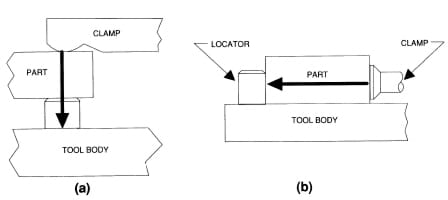
Figure 3-23. Clamps should always be positioned to direct the clamping force into the supports or locators.
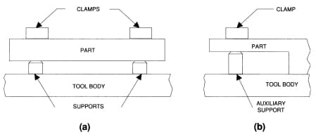
Figure 3-24. The workpiece and its supports determine the number and position of clamps.
Machine operation should not interfere with clamps. Ensure clamps don’t block or collide with machine parts during the machining cycle. Adjusting the cutter’s path can prevent collisions.
Low-profile clamps, like gooseneck clamps shown in Figure 3-25, help keep everything compact. Small contact areas increase pressure efficiency and reduce interference.
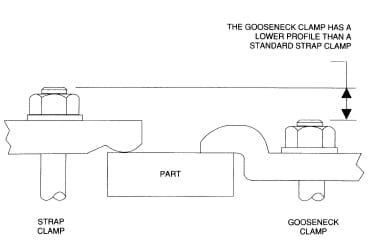
Figure 3-25. Using gooseneck clamps is one way to reduce the height of the clamps.
Always clamp the clamping force directly towards the locators or the strongest part of the workholder to prevent distorting the workpiece. Avoid clamping methods that put undue pressure on delicate parts, as shown in Figures 3-26 to 3-29. Use techniques like strap clamps or collets to distribute force evenly and prevent damage.
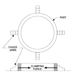
Figure 3-26. Directing the clamping forces against an unsupported area will cause this cylindrical part to deform.
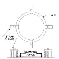
Figure 3-27. eliminate deformation by directing the clamping forces into the supports under the part.
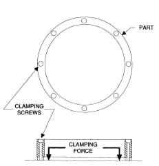
Figure 3-28. Part features such as holes can be used to clamp the part when possible.
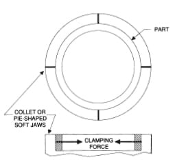
Figure 3-29. When the part can only be clamped on its outside surface, pie-shaped chuck jaws can hold it and reduce deformation.
Selecting Clamp Size and Force
Determining the necessary clamping force can be a complicated calculation.
In many situations, an approximate determination of these values is sufficient. The table in Figure 3-30 shows the available clamping forces for a variety of different-size manual clamp straps with a 2-to-1 clamping-force ratio.
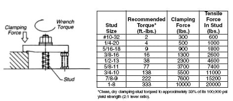
Figure 3-30. Approximate clamping forces of different-size manual clamp straps with a 2-to-1 clamping-force ratio.
Alternatively, we can determine the required clamping force based on calculated cutting forces. A simplified example is shown in Figure 3-31. The cutting force is entirely horizontal, and no workpiece locators are used, so frictional forces resist the cutting forces.
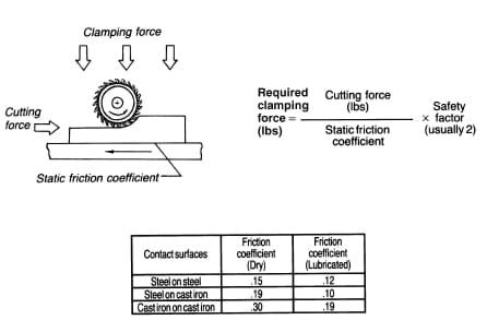
Figure 3-31. A simplified clamping-force calculation with the cutting force entirely horizontal and no workpiece stops.
When workpiece locators and multi-directional forces are considered, the calculations become more complicated.
The worst-case force situation can be estimated intuitively and treated as a two-dimensional static mechanics problem (using a free-body diagram) to simplify calculations. In the example shown in Figure 3-32, the cutting force is known to be 1800 lbs based on a previous calculation. The workpiece weighs 1500 lbs. The unknown forces are:
F R = Total force from all clamps on the right side
FL = Total force from all clamps on the left side
R 1 = Horizontal reaction force from fixed stop
R 2 = Vertical reaction force from fixed stop
R 3 = Vertical reaction force on the right side
N = Normal force = FL + FR + 1500
µ = Coefficient of friction = .19
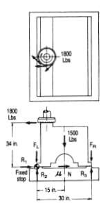
Figure 3-32. A more complicated clamping-force calculation using a two-dimensional free-body diagram.
The equations below solve for unknown forces, assuming that for a static condition:
- The sum of forces in the x direction must equal zero
- The sum of forces in the y direction must equal zero
- The sum of moments about any point must equal zero
At first glance, the example above looks “statically indeterminate, “ i.e., there are five variables and only three equations. But for the minimum required clamping force, R3 would be zero (workpiece barely touching), and FL would be zero (there is no tendency to lift on the left side). Now, with only three variables, we can solve:
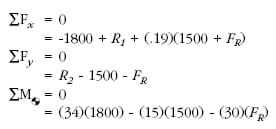
Solving for the variables,
FR = 1290 lbs
R1 = 1270 lbs
R2 = 2790 lbs
In other words, the combined force from all clamps on the right side must be greater than 1290 lbs. With a recommended safety factor of 2-to-1, this value becomes 2580 lbs. Even though FL (combined force from all the clamps on the left side) equals zero, a slight clamping force may be desirable to prevent vibration.
Another general area of concern is maintaining consistent clamping force. Manual clamping devices can vary in the force they apply to parts during a production run. Many factors account for the variation, including clamp position on the workpiece, but operator fatigue is the most common fault. The simplest and often best way to control clamping force is to replace manual clamps with power clamps.
The force generated by power clamps is constant and adjustable to suit workpiece conditions. Another benefit of power clamps is their speed of operation: not only are individual power clamps faster than manual clamps, but every clamp is activated simultaneously, ensuring consistency and a secure hold.
Browse Reliable and Versatile Clamps and Locators at Carr Lane Mfg.
Accurate location and clamping are essential for precise and repeatable machining, and at Carr Lane Mfg., we prioritize quality in all our products. Whether you need to find the perfect clamping solution or want to determine the best tools for location, our experts are here to help. To discover the best solutions for your application, explore our product catalog today.