Anatomy of a Ball Lock Pin
Understanding how Ball Lock Pins work begins with identifying the components that make up the mechanism.
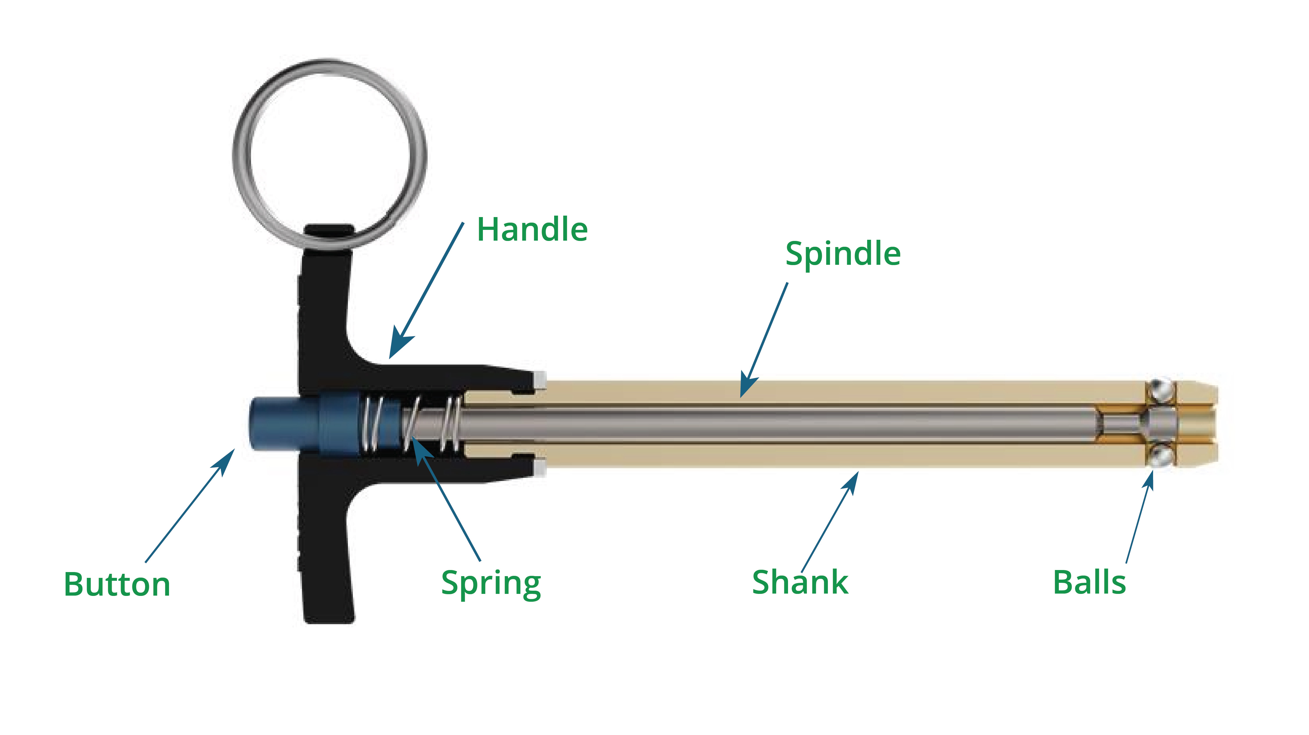
Handle
The grip end of the pin, designed for manual insertion and removal.
Button
The push-button actuator that controls the locking mechanism. When released, the pin is locked. When depressed, the pin unlocks.
Spring
An internal compression spring that provides the force to maintain the locked position. The spring continuously pushes the button outward and keeps the spindle retracted toward the handle.
Spindle
The internal shaft that moves axially when the button is depressed or released. The spindle has two critical features: a larger diameter section that cams the balls outward, and a reduced diameter section called the ball drop.
Ball Drop
A reduced-diameter section on the spindle. When the spindle moves forward and aligns the ball drop with the locking balls, the balls retract inward, allowing the pin to be removed.
Balls
Typically 2, 3, or 4 hardened steel balls that provide the locking function. These balls move radially in and out through holes in the shank.
Radial Holes
Holes machined through the shank wall that allow the locking balls to pass through. When the balls protrude through these holes, the pin is locked.
Shank
The cylindrical body of the pin that is inserted into the receiver hole. The shank houses the locking balls and provides the structural strength of the assembly.
Ball End
The insertion end of the pin. This is the end that enters the receiver hole first during installation.
Ball Lock Pin Action
Ball Lock Pins use a spring-loaded spindle mechanism to control the position of hardened steel balls. The balls move radially in and out of the shank, providing positive locking when extended and quick release when retracted.
Locked Position (Button Released)
In the natural, locked state, the button is extended outward from the handle. The internal spring keeps the spindle retracted toward the handle, positioning the larger diameter section of the spindle directly behind the locking balls.
This larger diameter section forces the balls outward through the radial holes in the shank. The balls protrude beyond the outer diameter of the shank and engage corresponding holes or grooves in the receiver component. The spring continuously applies force to maintain this locked position.
The pin cannot be withdrawn while the balls are extended. Any attempt to pull the pin creates a reaction force between the protruding balls and the receiver hole edges, which is transmitted through the balls to the spindle and ultimately to the entire pin assembly. The mechanical advantage strongly resists withdrawal.
Unlocked Position (Button Depressed)
To unlock the pin, the user depresses the button, pushing it inward toward the handle. This compresses the internal spring and moves the spindle forward, toward the ball end.
As the spindle moves forward, the ball drop aligns with the locking balls. The ball drop is a reduced-diameter section machined into the spindle specifically to provide clearance for the balls to move inward.
With the ball drop now aligned, the locking balls are no longer supported by the larger diameter section of the spindle. The balls fall inward into the ball drop, retracting within the outer diameter of the shank. The radial holes in the shank now contain only empty space where the balls previously protruded.
With the balls fully retracted, the shank diameter clears the receiver hole edges. The pin can now be freely inserted into or removed from the receiver.
Re-Locking (Button Released)
When the user releases the button, the compressed spring immediately extends, pushing the button back outward. This drives the spindle rearward, back toward the handle.
As the spindle retracts, the larger diameter section moves back into position behind the locking balls. The spindle cams the balls outward, forcing them through the radial holes and beyond the shank diameter.
If the shank is positioned in a receiver hole with corresponding locking holes or grooves, the balls snap outward into those holes. The user feels and often hears this engagement. The pin is now locked and cannot be withdrawn without depressing the button again.
If the shank is not aligned with receiver holes when the button is released, the balls contact the inner wall of the receiver hole and remain partially retracted. When the pin is rotated or adjusted to align the balls with receiver holes, the spring force immediately drives the balls outward into the locking position.
Single-Acting vs. Double-Acting Operation
Ball Lock Pins are available in two operational configurations: single-acting and double-acting. The difference lies in the spindle design and how the pin unlocks under load.
Single-Acting Ball Lock Pins
A single-acting pin has one ball drop on the spindle. The spindle can only move in one direction to unlock the balls. When the button is depressed, the spindle moves forward toward the ball end, aligning the ball drop with the balls and allowing them to retract.
In most applications, this presents no difficulty. However, when a single-acting pin is loaded in shear, the pin may be pressed firmly against one side of the receiver hole. If the button is on the opposite side of the applied load, the operator must depress the button while simultaneously pulling the pin in the direction opposite to the shear load. This requires the operator to work against both the spring force and the friction between the shank and receiver hole.
Double-Acting Ball Lock Pins
A double-acting pin has two ball drops on the spindle, one on each side of the balls. The spindle can move in either direction to unlock the balls. When the handle or ring is pushed or pulled, the spindle moves in whichever direction allows the balls to retract, regardless of how the pin is oriented or loaded.
This is particularly useful when pins are used in shear applications. The operator can push or pull the handle or pin in the same motion without fighting against the load direction. The spindle automatically moves in the direction that aligns a ball drop with the balls, allowing smooth withdrawal even when the pin is under significant side load.
Double-acting pins eliminate the need to determine handle orientation relative to load direction during removal. In production environments with frequent changeovers, this reduces operator effort and speeds disassembly.
Why This Mechanism Works
The Ball Lock Pin mechanism provides reliable, repeatable locking through deliberate engineering choices.
Positive Locking
The spring continuously applies force to keep the spindle retracted and the balls extended. The locked position is the natural, unpowered state of the mechanism. The pin cannot accidentally unlock. Withdrawal requires deliberate button actuation to compress the spring and move the spindle forward.
This creates a fail-safe condition. If the button mechanism experiences wear, damage, or contamination, the spring defaults to the locked position. The pin remains secured even if the button becomes difficult or impossible to actuate.
Spring Force and Load Distribution
The spring provides constant force to maintain ball extension. This force is distributed across all locking balls simultaneously, creating uniform load distribution in the receiver holes.
When the pin is subjected to shear or tensile loads during service, the force is transmitted through the extended balls. The hardened steel balls provide point contact with the receiver hole walls, concentrating load at specific locations. The receiver holes must be designed with adequate edge distance and material strength to support these concentrated loads without deformation.
Tactile and Audible Feedback
When the button is released after insertion, the user receives immediate tactile confirmation of engagement. The button extends outward from the handle, providing a clear physical indication that the locking mechanism has activated. This change in button position can be felt without looking at the pin or visually confirmed during inspection.
This feedback eliminates uncertainty during assembly. The operator knows immediately whether the pin has fully engaged and locked based on button position. An extended button indicates the balls have moved outward into the locking position. A depressed or partially depressed button indicates incomplete engagement or misalignment with the receiver holes.
Simplicity and Durability
The mechanism contains only a few moving parts: the button, spring, spindle, and balls. There are no threads, cams, or complex linkages to wear, bind, or require lubrication. The hardened steel balls operate in simple radial holes with clearance for contamination and wear.
This simplicity results in high reliability and long service life. Ball Lock Pins function effectively in environments with coolant, chips, and contamination that would disable more complex quick-release mechanisms.