Cam clamps are also based on the principle of the inclined plane. The most common forms of cam clamps are the eccentric cam and spiral cam. Depending on their arrangement, these cams can be used as directpressure clamps or indirect-pressure clamps.
Eccentric Cams
Eccentric cams, as their name implies, apply the clamping force with the action of an eccentric circle. As shown in Figure 8-71, these cams have a mounting hole positioned off center in the cam lobe. The off center location of the mounting hole produces the “rise,” the radial movement of the cam through its clamping cycle.
With eccentric cams, special care must be exercised to keep the cam locked during the clamping cycle. Eccentric cams only have one true locking point. This is the point at which the vertical center lines of the eccentric mounting hole and the lobe are perfectly aligned and exactly perpendicular to the clamped surface. Any other cam position cannot provide a positive lock. For this reason, eccentric cams are generally not suitable for workholding applications.
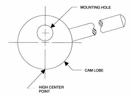 Figure 8-71. Eccentric cams should usually not be used for clamping because they do not provide positive
locking.
Figure 8-71. Eccentric cams should usually not be used for clamping because they do not provide positive
locking.
Spiral Cams
Continuous-rise spiral cams, through similar in appearance to eccentric cams, differ substantially in their operational principles. Rather than using an eccentric circle to achieve its rise, this cam has an involute curve on the clamping face of the cam. This design provides a wide range of clamping positions instead of just one. The two principal types of spiral cams are the single cam and the double cam, Figure 8-72.
The spiral design, although an improvement over the eccentric design, is still subject to loosening under heavy vibration. For this reason, a mechanical lock is a good idea for applications, such as extremely heavy milling, where considerable vibration can occur.
Direct-Pressure and Indirect Pressure Clamping
Cams are typically used in two styles of clamping, direct pressure and indirect pressure. As shown in Figure 8-73, direct-pressure cams apply the force directly to the workpiece (a). Indirect-pressure cams apply the clamping force through a secondary clamping element (b). The main objections to direct pressure clamps are the susceptibility of the clamps to vibration and the marring of the workpiece. The indirect pressure clamps are less prone to problems, but heavy vibration remains an issue.
 Figure 8-72. Spiral cams have a continuous rise to lock positively at any point in the clamping range.
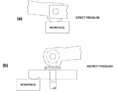 Figure 8-73. Indirect pressure cam clamps are safer because they are not affected by workpiece vibration.
The most suitable applications for cam clamps are where workpiece vibration is minimized. Drill jigs, light-to-medium-
duty milling fixtures, inspection fixtures, and assembly tools are all safe, effective applications for cam clamps.
Commercial Cam-Clamp Variations
Standard cam-clamp designs include cam-action strap clamps, cam edge clamps, up-thrust clamps, and cam action hold-down clamps. Each of these clamps has been designed to reduce the effects of vibrations and to maximize clamping efficiency.
Cam-Action Strap Clamps. Two examples of cam-action strap clamps are shown in Figure 8-74. The clamp shown at (a) has a standard slotted-heel clamp strap, while the clamp at (b) has a double-end clamp strap. Both clamps utilize an eye bolt and double cam, instead of the stud-and-nut assembly. Both these clamps apply indirect force to the workpiece through spiral cams, and are suitable for all but the heaviest machining with excessive vibration.
 Figure 8-74. Cam-action strap clamps.
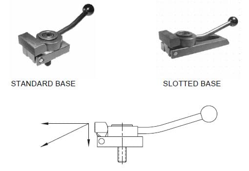 Figure 8-75. Cam-action edge clamps exert clamping force forward and downward at the same time.
Cam Edge Clamps. The cam edge clamp, shown in Figure 8-75, uses a horizontal single-cam handle with a
180º maximum throw. The pivoting nose element of the clamp applies force both forward and downward to securely hold the workpiece. These clamps are available with either a standard base for fixed-position mounting, or a slotted base for adjustable mounting.
Up-Thrust Clamps. The up-thrust clamp, Figure 8-76, is a unique clamp design. It holds a workpiece with
pressure from below. As shown at (b), pushing the cam handle down moves the clamping element upward against the workpiece. The underside of the top jaw element has a ground surface and acts as a precise locator for the clamped workpiece. This clamp is designed for workpieces that must be located and machined on the top surface.
Cam-Action Hold-Down Clamps. The cam-action hold-down clamp, shown in Figure 8-77, is another clamp that uses a cam-action to apply holding force. The cam here is also a spiral design with a 2-1/2º wedge angle. It permits a clamping range of 3/16”. This clamp is made of cast steel with flame-hardened wear points. The solid arm can be used to clamp workpieces directly, or tapped to mount a threaded clamp spindle.
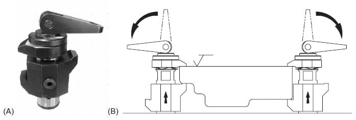 Figure 8-76. Up-thrust clamps apply force by cam action.
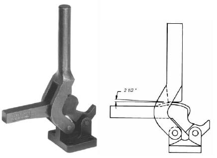 Figure 8-76. Cam-action hold-down clamps use a 2-1/2º spiral cam to achieve a clamping range of 3/16”.