Hydraulic systems are integral to many manufacturing and industrial applications, providing the power and precision required for efficient and reliable operations. Understanding hydraulic symbols and diagrams is essential for designing, maintaining, and troubleshooting hydraulic systems. These symbols act as a universal language, providing a clear representation of how each hydraulic component functions in a hydraulic system.
Hydraulics engineers regularly encounter these diagrams, but these symbols can be daunting to interpret if you have limited experience with schematics and the fluid power industry. In this article, the experts at Carr Lane Mfg. guide you through the basics of hydraulic symbols and diagrams, offering insights into their meaning and significance in power workholding systems. Whether you’re an experienced engineer or new to hydraulic design, understanding these symbols will help you optimize your system’s performance and ensure seamless integration into your manufacturing operations.
Basic Symbols Representing Hydraulic Components
Hydraulic systems use a variety of symbols to represent the components and flow paths within a hydraulic system. These symbols are standardized, making it easier for engineers and technicians to understand and design systems. Here’s a breakdown of the primary types of symbols.
Circles and Semi-Circles
Circles and semi-circles are used to represent rotary devices such as pumps, motors, and reservoirs. These symbols provide a visual shorthand for the essential elements that generate and manage hydraulic power. When circles or semi-circles are used, triangular arrows represent the direction fluid takes in the pump or motor. For example, when a circle represents a pump, the arrow faces outward, but when it represents a motor, the arrow faces inward. However, motors are often bi-rotational, meaning fluid can enter either port. In this instance, the circle will have triangles at both the top and the bottom.
A full circle typically represents rotary components such as hydraulic pumps or motors. Semi-circles are often used to depict hydraulic reservoirs or tanks. For instance, a semi-circle open at the top may represent a vented reservoir, while a closed semi-circle might indicate a pressurized one.
Diamonds
Diamonds represent conditioning devices like filters, heaters, and coolers. These components play a vital role in maintaining system cleanliness by removing contaminants from the hydraulic fluid. A single diamond with lines across it often indicates a filter. Additional markings, such as arrows, may show the direction of flow through the filter. Strainers are also depicted with diamond symbols, but they may include a mesh pattern to differentiate them.
Back-to-Back Semi-Circles and Arrowheads
Back-to-back semi-circles and arrowheads represent flow control elements like valves, either viscosity dependent or viscosity independent. Valves control the direction, pressure, and flow of hydraulic fluid. Directional control valves are often shown as rectangles divided into sections, with arrows inside to indicate the flow path. Back-to-back semi-circles within the valve symbol may represent pilot control mechanisms. Arrows combined with semi-circles are used to illustrate adjustable or fixed flow rates within the system.
Saw Tooth Symbols
Saw tooth symbols represent springs, which are integral components in many hydraulic valves. Springs provide force to return or hold a component, such as a valve spool, in a specific position. Their presence in the diagram illustrates how the valve or mechanism is actuated or reset.
A single saw tooth symbol is commonly used to indicate a spring-loaded mechanism. For example, it might represent the spring used to return a directional control valve to its default position when no external force is applied. In some cases, double saw tooth symbols are used to show opposing springs or more complex spring assemblies within the hydraulic system.
Lines
In hydraulic power diagrams, lines are another commonly used symbol. They represent the flow paths and connections between components, with different line styles and patterns providing specific information about the type of connection.
Continuous, solid lines represent main flow lines where hydraulic fluid is actively circulating under pressure. Dotted lines indicate pilot signals and drains, where hydraulic fluid is routed back to the reservoir after performing its function. Dash-dot lines are used to show an enclosure outline that represents a grouping of components like a directional control valve.
How Hydraulic Symbols Work Together

Hydraulic symbols form a universal language that represents the intricate functionality of hydraulic systems. By combining individual symbols in various configurations, engineers can illustrate actual machines and systems with clarity and precision. These symbols are not standalone elements but work together to create a visual roadmap of how hydraulic components interact within a system.
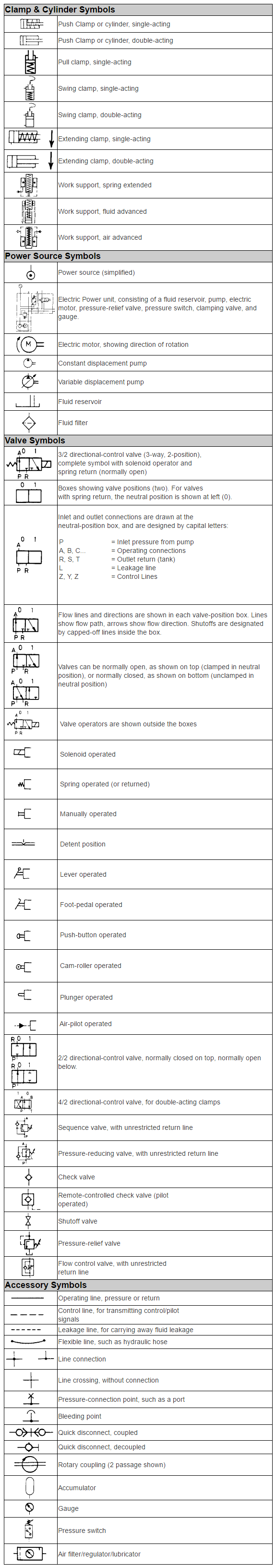
The examples provided are only a sampling of commonly used symbols. Each symbol corresponds to a specific component or function, and when combined, they depict the complete flow, control, and power distribution of a hydraulic circuit. Below is our hydraulic symbiology glossary, outlining elements of specific Carr Lane ROEMHELD parts.This glossary includes symbols for components such as:
- Check Valves: Ensure fluid flows in one direction while preventing reverse flow.
- Power Units: Represent the hydraulic system’s primary source of power.
- Relief Valves: Depict pressure-limiting devices that protect the system from over-pressurization.
- Control Valves: Show the components that regulate flow direction, pressure, and speed.
- Pressure Gauges: Indicate fluid pressure within the system for monitoring and troubleshooting.
- Hydraulic Circuits: Illustrate the complete layout of interconnected components in the system.
- Variable Displacement Pumps: Represent pumps capable of adjusting output flow based on system requirements.
Component-Specific Symbols: The Complete List