Clamping force plays a crucial role in ensuring the stability and accuracy of machining operations. By understanding how to calculate clamping force, you can ensure that your workpiece remains securely in place during the machining process.
This article will guide you through determining the appropriate clamping force for your application and provide insights into measuring and calculating these forces. Additionally, it offers valuable information on the importance of selecting the proper clamps. It provides recommendations for finding the ideal clamp for your specific needs.
Whether you are a seasoned professional or a novice, mastering clamping force calculation will improve machining outcomes and overall efficiency. To quickly determine the clamping force needed for your application, you can use the calculator below, clicking or typing to input the numbers associated with your machinery and materials.
What is Clamping Force?
Clamping force is the amount of force applied to a workpiece by closing and locking a clamp. Calculating clamping force provides a clamp with the adequate capacity to resist external machining forces, making it an essential metric for accurate machining. To determine the clamping force for your application, there are several factors to consider, including cutting force and workpiece material.
The Importance of Calculating Clamping Force
If clamping force is insufficient, it can result in the workpiece shifting or moving during machining, leading to inaccuracies, poor surface finish, and even damage to the workpiece or the machine itself. On the other hand, excessive clamping force can deform or distort the workpiece, affect its dimensional accuracy, or even cause damage to the clamps or fixtures. Because clamping force plays such a large role in the outcome of machining processes, accurately calculating it is essential.
Determining the Appropriate Clamping Force
As we briefly mentioned, several factors come into play when determining the right amount of clamping force for your specific application.
One of the primary considerations is the cutting force exerted during machining. Cutting forces are generated due to the interaction between the cutting tool and the workpiece material. The clamping force must be high enough to counteract the cutting forces but not so high as to deform the workpiece. Cutting forces can vary depending on factors such as the machined material, the tool geometry, cutting parameters, and the depth of cut, making it vital to design your clamping setup to accommodate the highest anticipated cutting forces while still protecting the workpiece.
It is also essential to consider the clamp or clamping mechanism used. Different clamps have varying capabilities and limitations when providing clamping force. Factors such as the design, size, condition of the clamp, and the contact area between the clamp and the workpiece can affect the achievable force.
How to Measure Clamping Force
Measuring clamping force can be a complex task that requires careful calculations. However, in some cases, an approximate method can provide sufficient information. One way to estimate clamping force is by comparing the clamping force ratio to the available force from manual clamp straps. These measurements can be instrumental when comparing them with power-clamp forces.
The clamping force ratio refers to the ratio between the force applied to the clamping mechanism and the resulting force exerted on the clamped object. For example, a 2-to-1 clamping-force ratio means that for every unit of force applied to the clamping mechanism, two units are generated to hold the object in place.
See the table below for how much clamping force is available from manual clamp straps of various sizes (with a 2-to-1 clamping-force ratio) to compare with power-clamp forces.
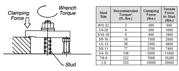
| Stud Size |
Recommended Torque* (ft.-lbs.) |
Clamping Force (lbs.) |
Tensile Force In Stud (lbs.) |
| #10-32 |
2 |
300 |
600 |
| 1/4-20 |
4 |
500 |
1000 |
| 5/16-18 |
9 |
900 |
1800 |
| 3/8-16 |
16 |
1300 |
2600 |
| 1/2-13 |
38 |
2300 |
4600 |
| 5/8-11 |
77 |
3700 |
7400 |
| 3/4-10 |
138 |
5500 |
11000 |
| 7/8-9 |
222 |
7600 |
15200 |
| 1-8 |
333 |
10000 |
20000 |
*This table depicts a clean, dry clamping stud torqued to approximately 33% of its 100,000 psi yield strength (2:1 lever ratio).
You can also calculate the required clamping forces based on the calculated cutting force. A simplified example appears below, with the cutting force entirely horizontal and no workpiece stops (frictional force resists the entire cutting force).
Understanding Complex Clamping Force Calculations
With workpiece stops and multi-direction forces, calculations become much more complicated. To somewhat simplify the process, intuitively determine the worst-case force situation, then treat the calculation as a two-dimensional static mechanics problem (using a free-body diagram).
In the example below, the cutting force is already known to be 1,800 lbs from previous calculations. The workpiece weighs 1,500 lbs. Unknown forces are:
FR = Total force from all clamps on the right side
FL = Total force from all clamps on the left side
R1 = Horizontal reaction force from fixed stop
R2 = Vertical reaction force from fixed stop
R3 = Vertical reaction force on the right side
N = Normal force = FL + FR + 1500
µ = = Coefficient of friction = .19
The equations below solve for unknown forces, assuming that for a static condition:
- The sum of forces in the x direction must equal zero
- The sum of forces in the y direction must equal zero
- The sum of moments about any point must equal zero
At first glance, the example above looks “statically indeterminate,” meaning there are five variables and only three equations. But for the minimum required clamping force, R3 would be zero (workpiece barely touching), and FL would be zero (there is no tendency to lift on the left side). Now, with only three variables, we can solve the following:
In this case, we are solving for the variables FR, R1, and R2, which net out to:
FR = 1290 lbs
R1 = 1270 lbs
R2 = 2790 lbs
In other words, the combined force from all clamps on the right side must be greater than 1290 lbs. We recommend a 2-to-1 factor of safety (2580 lbs). Even though FL (the combined force from all clamps on the left side) equals zero, a slight clamping force may be desirable to prevent vibration.
However, it’s important to note that too much force can be as detrimental as too little. Excess force can cause fixture and machine-table distortion or even damage. Even a small hydraulic clamp can generate tremendous stress (S).
In the example above, three 4,560-lb Edge Clamps cause some machine-table bending. Using static beam-binding calculations, the maximum distortion at point D is about .0006 inches (which is probably acceptable depending on your specific application).
However, the distortion would be much more significant if the clamping point were higher off the machine table (P dimension). Higher clamps would require an added intermediate fixture plate to increase table rigidity.
Find the Right Clamp for Your Application at Carr Lane Mfg.
Carr Lane Mfg. offers a complete line of industrial clamp straps with clamping force capacities ranging from 300 to 10,000 lbs. These extremely versatile clamping devices can exert considerable holding force and are available in a variety of materials, including steel, stainless steel, and aluminum. With the necessary clamping force determined, you can find the best heavy-duty clamp straps for your application in the Carr Lane Mfg. catalog.