Locating pins are precision-engineered components that accurately position and align parts in a workholder. They play a critical role in ensuring that components fit together perfectly, which is essential for maintaining the integrity and functionality of the final product. They can be constructed from a wide range of materials and come in a variety of types to fit many manufacturing applications and processes.
Carr Lane Mfg. is known for our high-quality locating pins, and we offer many different forms to fit your exact needs: pin locators, round locating pins, bullet-nose and conical locators, diamond locating pins, floating locating pins, and locator plugs.
Understanding the Different Types of Locating Pins
The primary function of locating pins is to guide and securely hold a workpiece in a predetermined position on a fixture or during the assembly process. This helps reduce errors during machining or assembly, leading to consistent product quality. There are many types of locating pins available in different materials and coatings to fit different manufacturing processes.
Pin Locators
The most common form of locator is the pin type, shown in Figure 7-2. Pin locators are available in two basic styles, either plain or with a shoulder. Both styles come in a wide range of diameters and are typically installed by either press fitting the pin directly into the tool body or by slipping the pin into a bushing.
Plain locating pins are simply cylindrical pins with a smooth surface. They are used primarily for positioning parts with minimal load-bearing requirements and fit into corresponding holes on the workpiece or fixture. Their simplicity makes them versatile in various applications where high precision is not critical, but proper alignment is necessary. Plain locating pins are pressed directly into the tool body. They are normally used for workholders in short-to-medium production runs where there is no need for pin replacement, providing the necessary horizontal location, in the x and y axes, for the workpiece.
Locating pins with a shoulder feature a distinct shoulder or flange at one end, which provides a critical stopping point for the workpiece. It acts as a physical stop that prevents the pin from being inserted too deeply into the receiving hole and can bear greater loads, making them suitable for applications with high workpiece weights. Unlike plain pins, shoulder-type pins are made in two styles: press-fit type and lockscrew, as illustrated in Figure 7-3. The press-fit type is pressed into the tool body in the same way as a plain-type locating pin. The lockscrew type, however, should be installed with a locating pin liner bushing.
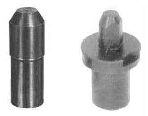
Figure 7-2. Two common types of locating pin: plain and shoulder-type.
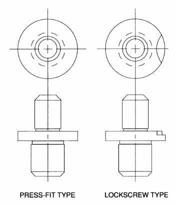
Figure 7-3. Shoulder-type locating pins are made in two styles; the press-fit type for permanent installation and the lockscrew type with a slip fit for renewable installation.
Round Locating Pins
Round locating pins are distinguished by their cylindrical shape, which is straightforward yet effective for a wide variety of applications. They can be used for both internal and external workpiece location and are typically manufactured to precise tolerances to ensure a snug fit within the workpiece holes.
For internal location, the diameter of the pin must match the size of the locating hole. These locators come in many standard sizes and are readily available ground to special diameters. For external location, the size of the locating pin is not as critical. Here, a standard pin size strong enough to resist machining forces is the best choice.
When installing lockscrew-type round locating pins, a liner is pressed into the tool body and affords the locating pins a hardened, wear-resistant mounting hole. The machined recess on the shoulder is for a lockscrew that holds the locating pin in position. The liner is primarily intended for workholders in long production runs or for applications where heavy wear is a concern. Locating pin liners permit the easy and accurate replacement of the locating pins as they wear without damaging the mounting holes or having to remove the fixture plate from the machine tool.
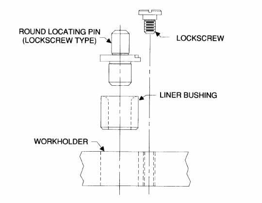
Figure 7-4. Liner bushings and lockscrews are usually used to mount renewable locating pins.
Bullet-Nose and Conical Locators
In addition to the round locating pins previously mentioned, other variations are available, including bullet-nose dowels, bullet-nose pins, and cone locator pins. These end shapes are mainly for internal location and allow easier loading of workpieces over the pins. Each of the locators is installed by press fitting into the tool body.
Bullet-nose dowels are designed with a rounded, bullet-shaped tip for easy insertion and alignment. These dowels are typically used with bushings to guide the assembly of two parts with high precision. Bullet-nose dowels are commonly used in fixture setups where parts need to be quickly and frequently aligned and disassembled, such as in modular fixtures. Like bullet-nose dowels, bullet-nose pins also feature a rounded tip but are generally used as permanent or semi-permanent guides in assembly operations, serving as both a locating and holding device. These pins are particularly useful in automotive, aerospace, and industrial machinery manufacturing, where precision assembly of large components is required.
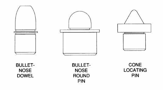
Figure 7-5. These round locating pins have unique head shapes for specialized applications.
The most common application for these locating pins is the alignment of workholder elements, rather than locating workpieces. A sandwich jig, for example, is made with two individual plates. Two locating pins ensure the alignment of the top plate to the bottom plate when the jig is assembled. In these cases, the locating pins are aligned with locating bushings to help maintain locational accuracy throughout the life of the workholder.
Bullet-nose pins are ideal for aligning two pieces of a workholder. The pin’s shank diameter and the locating bushings’ outside diameter are the same size, which allows for boring the installation holes in both pieces at the same time. This approach achieves greater accuracy.
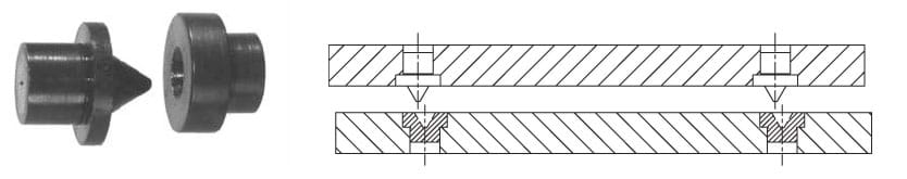
Figure 7-6. Cone locator pins compensate for misalignment to achieve the quick assembly of two workholder pieces.
Cone locator pins have a conical shape that narrows towards the tip, allowing for easier alignment and insertion compared to cylindrical pins. Cone locator pins are used with mating bushings, as shown in Figure 7-6. These medium accuracy locating pins compensate for a significant amount of misalignment to allow quick assembly of two workholder pieces. Cone locator pins are ideal for applications requiring rapid and precise alignment in high-volume production settings and are also used in operations where the components have a tendency to shift or expand due to temperature.
Diamond Locating Pins
Another style of locating pin frequently seen in jig-and-fixture design is the diamond, or relieved, locating pin. Like round locating pins, diamond pins are available in either the plain or shoulder-type, as shown in Figure 7-7. Their distinctive feature is the diamond-shaped tip, which allows for precise control over the orientation of the part being positioned. To limit the pin’s contact area, the diamond locating pin is made with four machined flats. The exact width of the contact area varies with the size of the pin and is usually equal to one-third of the diameter on each side.
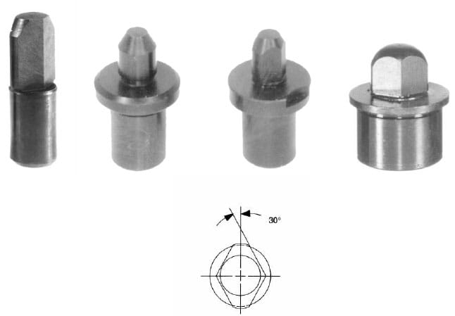
Figure 7-7. Diamond locating pins are relieved to locate in only one axis. They are available in configurations to match round locating pins.
Diamond pins are generally used as shown in Figure 7-8. Here the diamond pin acts as a radial locator to restrict radial movement of the workpiece around the concentric locator, shown by the round-pin locator. Since a diamond pin locates in only one axis, the contact areas of the pin must be positioned as shown. Positioning the pin any other way would allow the part to move about the concentric locator. Plain diamond pins are available with three standard pilot diameters, designated as X, Y, and Z, with X having the tightest location tolerance, and Z the loosest.
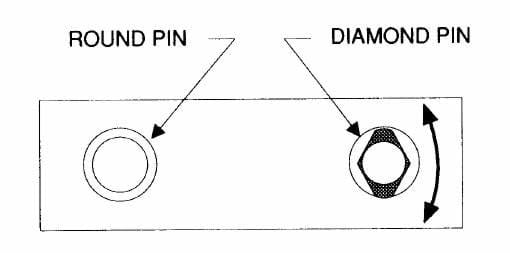
Figure 7-8. Diamond pins are relieved to act only as radial locators, avoiding the redundant location that causes binding during loading.
Floating Locating Pins
Another locating pin that corrects slight differences between locating holes is the floating locating pin. These specialized type of locating pins are designed to provide flexibility and accommodate misalignments between holes, making them particularly useful in scenarios where precision alignment is challenging due to inconsistencies in part manufacturing or thermal expansion. The floating locating pin provides precise location in one axis but moves up to 1/8" in the perpendicular axis. The body of the locator is referenced to the fixed and movable axes with a roll pin.
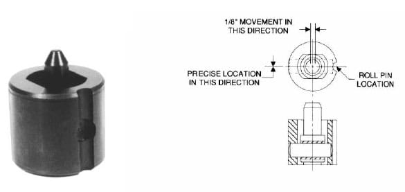
Figure 7-9. A floating locating pin provides precise location in one axis and allows up to 1/8" movement in the perpendicular axis.
The floating locator performs the same function as a diamond pin, but is able to move or float within a controlled range. Due to the pin’s floating movement, this locator can be used for parts with looser locational tolerances between the holes. As shown in Figure 7-10, the floating locating pin is often used with a round locating pin. Many floating pins also include self-centering features that help align and secure the parts as they are assembled, reducing the need for manual adjustments and speeding up the assembly process without compromising accuracy.
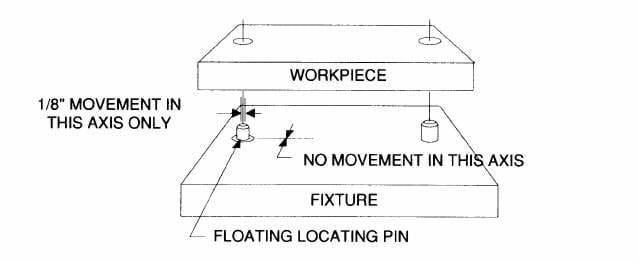
Figure 7-10. Floating locating pins are used with round locating pins to compensate for significant variations in hole spacing.
Locating Plugs
Locating plugs are simply large locating pins, typically used in larger or differently shaped holes. Standard locating pins are usually available only up to 1.00" in diameter, but locating plugs often have features to help them accommodate variations in hole sizes or shapes. Larger plugs are usually pressed into the tool body, then held in place with screws or dowel pins, as shown in Figure 7-11. Smaller plugs can be installed with a mounting diameter that has both a press-fit area and threads. In either case, the press-fit diameter locates the plug in the workholder. In modular fixturing set ups, or fifth axis applications, standard fixture keys are available in 25, 30, and 50 millimeter sizes. These are usually found in pallet applications as the center locator, using a radial pin to achieve proper orientation of the fixture plates, which are often round. For fifth axis applications, central locators are available with one end 25mm in diameter, and the other in a range of sizes from ½" up to 3.25" in both inch and metric diameters.
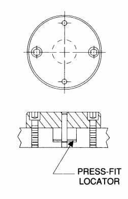
Figure 7-11. Locating plugs can be custom-made to locate workpieces on larger internal diameters.
As another option, a series of locating pins can take the place of a locating plug. As shown in Figure 7-12, the pins are positioned at three points, 120 degrees apart, around the internal diameter of the hole. This arrangement is usually much more economical than making a custom plug.
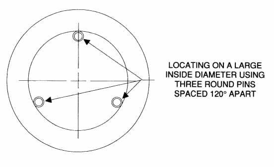
Figure 7-12. Instead of making a special locating plug, three locating pins, spaced 120º apart, can be used for locating large diameters.
Find the Perfect Locating Pin for Your Application at Carr Lane Mfg.
Locating pins are essential in nearly all manufacturing processes, ensuring that workpieces are correctly aligned and secured during assembly and machining. As part of our inventory of high-quality industrial parts, Carr Lane Mfg. offers a variety of locating pins suited for different applications and materials. To find the best locating solution for your operation, explore our locating pin selection and connect with an expert today.
Discuss Your Needs with Carr Lane Mfg.