Work Supports Guide
Work supports, like other locators, are made in many forms to suit varied applications. The specific choice of work supports is usually determined by the kind of support required, fixed or adjustable.
Rest Buttons and Plates
Rest buttons and plates are the primary devices for supporting a workpiece in a jig or fixture. As shown in Figure 7-24, standard rest buttons are available with either flat or spherical contact surfaces in a wide range of sizes. The buttons are typically hardened to reduce wear on the contact surface. Rest buttons with a flat contact are used when a small area contact on the workpiece is needed. The spherical-style button is best when point contact is preferred.
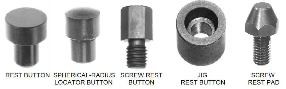 Figure 7-24. Standard forms of rest buttons.
Rest buttons are usually either press fit, threaded, or screw mounted, as shown in Figure 4-25. The head height of a rest button is closely controlled to ensure accuracy.
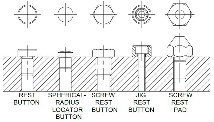 Figure 7-25. Rest buttons are (usually) either press fit, threaded, or screw mounted.
Rest plates, like rest buttons, are also available in several sizes and thicknesses, Figure 7-26. The plates act in the same way as rest buttons, but are mainly for larger or heavier workpieces. The plates are installed with Socket-Head Cap Screws rather than with a shank-type mount. The large pad area reduces contact pressure on the part.
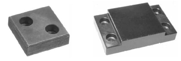 Figure 7-26. Jig leg plates and heavy duty rest pads support larger or heavier workpieces.
For most applications, rest buttons and plates are much better than locating surfaces machined directly into the tool body. Since the buttons and plates are mounted to the tool body, they are easily replaced when they wear. Workholders with locators machined directly into the tool body, on the other hand, are not as easily repaired.
The overall accuracy of rest buttons and pads is sufficient for all but the most critical applications. Typically rest buttons and plates are accurate to -.000/+.001”, while heavy duty rest pads are accurate within .0005”. In cases where more accuracy is required, locating surfaces can be reground. The simplest way to ensure that the height of the rest buttons or pads are all the same is to install them, then take a light pass across the contact surfaces with a surface grinder (rest buttons are typically through-hardened to allow regrinding). This procedure works only on locators with a flat contact, not with a spherical contact.
Another form of rest pad is the swivel contact bolt, Figure 7-27. These supports have a precision swivel ball that adjusts to curved, sloped, or uneven surfaces to provide full contact. Swivel bolts are also available with serrated round gripper inserts (hardened tool steel or carbide) for additional holding force. Serrated grippers slightly penetrate the workpiece surface to provide significantly more resistance to sliding than from static friction alone.
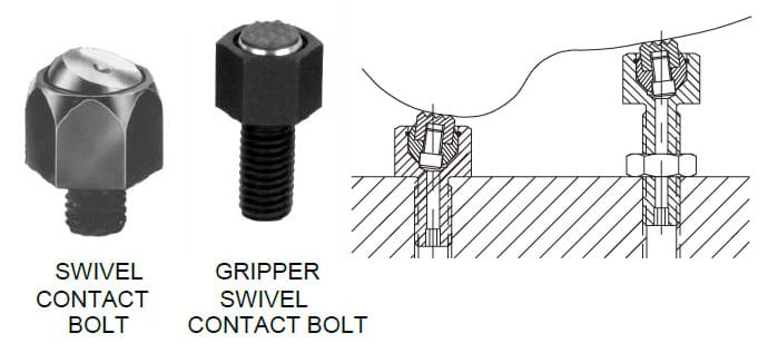
Figure 7-27. Swivel contact bolts are rest pads that adjust to uneven surfaces. They are also available with round gripper inserts to increase holding force.
Jig Feet
Jig feet are devices that locate the entire workholder, or jig, rather than a workpiece. Two common styles are drill-jig feet and double-end feet. Drill-jig feet, Figure 7-28, are mounted on the bottom side of a jig to provide a stable, elevated base for the jig. The feet are mounted on the tool body with a socket-head cap screw; then doweled in place to prevent rotation.
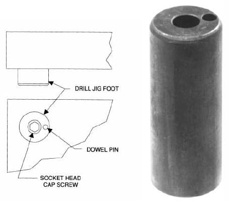 Figure 7-28. Drill jig feet are mounted on the tool body to provide a stable elevated base for the jig.
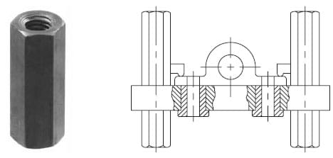 Figure 7-29. Double-end jig feet are available in many different lengths, and are used for jigs that are turned over.
The double-end jig feet are designed for jigs that are normally used on two sides. The feet are installed on the tool body with studs. As shown in Figure 7-29, one jig foot is installed on one side of the jig and a second foot is mounted on the other side. A stud threaded into both feet securely holds the feet together. Double-end jig feet are generally found in jigs that perform operations on two opposite sides of a part. They are available in several lengths, and different lengths are often used together. Double-end jig feet are also useful for jigs that are flipped over to remove the workpiece. Such construction permits the jig to be flipped over for part loading without resting the jig on the heads of the drill bushings.
For applications where only additional height is needed and the jig will not be flipped over, as with some table jigs, only one set of jig feet is needed, as seen in Figure 7-30. Rest buttons and plates are also frequently used as jig feet.
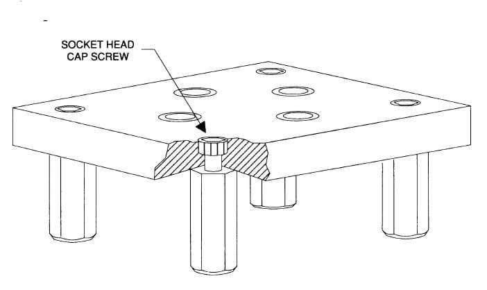 Figure 7-30. A single set of jig feet may also be used for table jigs where only additional height is needed.
Screw Jacks
One other device that frequently supports workpieces is the screw jack. Screw jacks are a form of adjustable support. This type of support can be used with almost any workpiece, but it is most common with cast or forged parts.
Screw jacks, the most common adjustable support, rely on a screw thread for adjustment. Figure 7-31 shows three variations. The first is the adjustable locating button. The locator has a hexagonal area for adjusting the locator with a wrench. A lock nut prevents movement once the proper height is set.
The other two styles rely on a knurled head for adjustments. The knurled screw jack is a general purpose device used in applications where the contact force of the support will not move the part. When a specific contact force is desired, however, the torque screw jack should be used. This support is well suited for parts with thin cross sections where excessive pressure can distort the part. Once again, a check nut or lock nut is used to prevent movement once the support height is set.
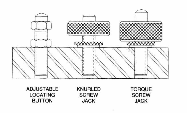 Figure 7-31. Screw jacks are a common type of adjustable support that use a screw thread for adjustment.
A fourth style of screw jack is the heavy-duty screw jack shown in Figure 7-32. This screw jack differs from the others in both its construction and the way it is mounted. The unit is mounted on, instead of threaded into, the baseplate. Heavy-duty screw jacks can be used alone or with riser elements to extend the height of the unit. The interchangeable contact tips adapt the jack to various workpiece shapes.
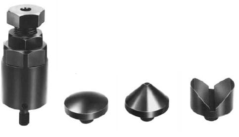 Figure 7-32. The heavy-duty screw jack uses a variety of tips for different part shapes. It can be mounted directly on the baseplate or elevated with riser elements.
Adjustable supports are normally used as secondary supports in combination with solid supports. In most cases these solid supports are the primary locating points, while adjustable supports provide additional stability, as shown in Figure 7-33.
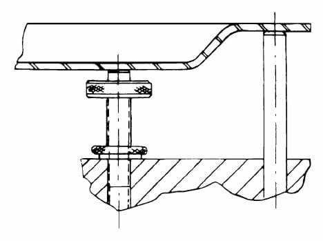 Figure 7-33. Adjustable supports, such as this screw jack, are normally used as supplemental supports along with solid rests.
Manual Work Supports
Manual work supports, Figure 7-34, are spring-loaded devices that generally work in combination with solid supports. The support provided is usually secondary rather than primary. Manual work supports provide additional support for thin sections, extended projections, or other workpiece areas that are difficult to support.
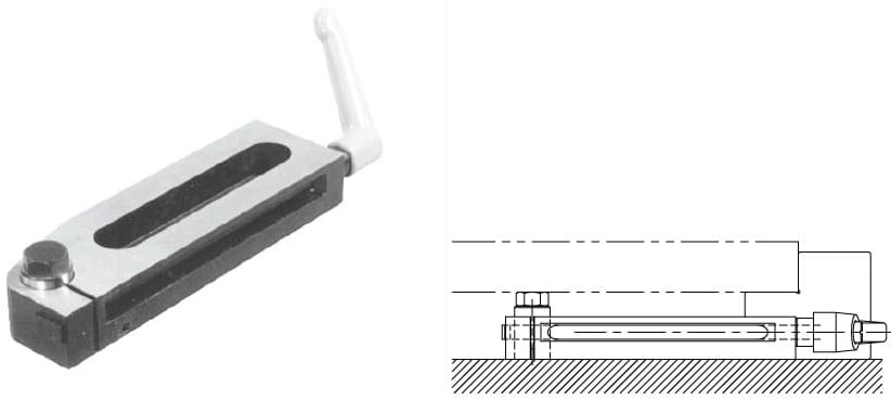 Figure 7-34. Manual work supports have a spring-extended plunger that is locked by tightening the handle. Their low profile allows reaching underneath low workpieces.
These work supports adjust to different supporting heights with a spring-loaded plunger mechanism. The extended plunger floats while the workpiece is loaded and clamped. Turning the adjustable handle locks the plunger securely. Alternatively, the plunger can also be locked in retracted position for unobstructed loading. A threaded hole in the plunger accepts a locating screw to extend the height(s) of the support.
Manual work supports also dampen vibration. When positioned under large unsupported areas of the part, the supports maintain contact with the part and eliminate much of the chatter caused by vibration.
Hydraulic Work Supports
Hydraulic work supports, Figure 7-35, also provide adjustable support for irregular or thin areas of a workpiece. Hydraulic supports are more precise and have greater load capacity than manual work supports. The three common forms of hydraulic work supports are the spring-extended, fluid-advanced and air-advanced styles, as shown in Figure 7-36. The spring-extended type holds the plunger in contact with the workpiece with an internal spring action. The fluid-advanced type advances the plunger with light hydraulic pressure. The airadvanced type moves the plunger into initial contact with the workpiece with air pressure. Once the workpiece is contacted, however, all three styles hydraulically lock the support in position.
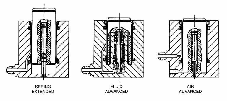 Figure 7-36. The three forms of hydraulic work supports are the spring-extended, fluid-advanced and air-advanced styles.
Hydraulic work supports do not exert clamping force on the workpiece. Instead, they automatically adjust their plunger height to suit the workpiece. Once positioned, they lock in position and become fixed, precision supports. Several sizes and mounting styles are available to suit almost every application.
Levelers
Levelers are fixturing devices used for a variety of workholding applications. Levelers are often installed in a baseplate to level the complete workholder. They may also level supports for workpieces as well. The major forms of levelers are shown in Figure 7-37. They include jig feet leveling assembly, leveling feet, jig leveling feet, stud leveling feet, swivel pads, and swivel nuts.
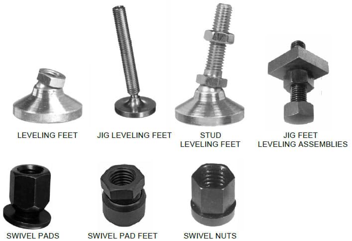 Figure 7-37.Levelers are used both for leveling entire workholders and for supporting workpieces.
A common feature of the levelers is their swivel contact pad. This is true for all but the swivel nut, and the jig feet leveling assembly, which has no pad. The swivel contact pad on each of the levelers has a ball mount, which permits the leveler to be adjusted without rotating the pad. While the leveler is adjusted by turning the threaded body, the pad remains stationary. This prevents workpiece movement and reduces the chance of marring. Other ways to prevent marring are through the substitution of nylon pads on the leveling pads and stud leveling pads, or adding rubber pad covers to the leveling pads or stud leveling pads. Rubber pad covers help prevent sliding on sloped or uneven surfaces. The swivel nut allows turning a screw body without rotating the contact pad, but does not pivot.
Another style of leveling device is the eccentric leveling lug, Figure 7-38. These levelers most often level tool bodies rather than workpieces. The eccentric leveling lug is first mounted to the tool body through the counterbored mounting hole. The lug is then rotated to the desired height, and the mounting screw is tightened. To permanently fix the location, the lug is doweled in place.
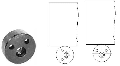 Figure 7-38. Eccentric leveling lugs use a rotary eccentric action for leveling. Once set, they are fixed in place with dowel pins.