Alignment pins are essential components that serve a variety of functions in jigs and fixtures. Most commonly, these devices align the workpiece to the workholder or position removable workholder elements. Alignment pins come in many types, styles, and sizes for many applications and are typically made from steel or other alloy steels, ensuring precise alignment within fixtures to maintain machine accuracy, efficiency, and performance. Each type of alignment pin is best suited for specific industrial workholding needs, and in this guide, Carr Lane Mfg. explores the various types available to help you determine which is best for your operation.
Plain Alignment Pins
Plain alignment pins are the simplest form of alignment pin and are available in five primary types: L pins, T pins, jig pins, shoulder pins, and clamping pins. Each is made with a precise diameter locating pin to ensure proper alignment and is typically crafted from hardened steel, stainless steel, or alloy materials to provide durability and resistance against wear and corrosion. All types (minus the clamping pin) have a bullet-nose end for easy insertion into the mounting holes. The clamping pin has a threaded end to permit a fixed installation and comes with a bushing that is positioned and fixed at assembly. Plain alignment pins are commonly used in settings that require precise alignment, such as automotive, aerospace, and manufacturing assembly lines. Because these pins lack complex mechanisms, they are easy to handle and operate, which is especially beneficial in fast-paced industrial environments.
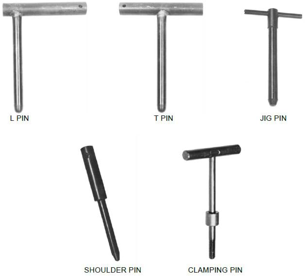
Figure 7-57. Alignment pins are used to accurately line up holes, with five available styles for plain alignment pins.
The specific mount for the alignment pins is determined by the application. In some cases, the pins are installed in drilled and reamed holes, but when looking to achieve more precision or for longer production runs, they may be installed in hardened bushings. Slotted locator bushings, illustrated in Figure 7-58, are used to line up two sets of holes without binding. The design of these bushings is like that of floating locating pins and permits movement in only one direction. As shown, the bushings are installed and correctly aligned in the mounting plate with a dowel pin. Slotted bushings are also available with a knurled outside diameter. These bushings can be either cast in place or potted in a plastic compound.
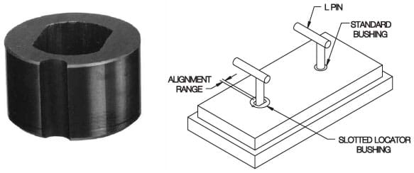
Figure 7-58. Slotted locater bushings are used with alignment pins to line up two sets of holes without binding.
Locking Alignment Pins
In addition to the plain style, L pins, T pins, and clamping pins are also available with locking bushings. Locking alignment pins are used to secure the alignment of components in assemblies where vibration or incidental movement may dislodge standard pins. As shown in Figure 7-59, locking pin bushings are installed in the mounting plate and securely attach the alignment pin to the plate, locking in place once inserted to provide a secure hold. The spring clip ring in the locking pin bushing holds the alignment pin in its retracted position by engaging the groove at the end of the pin. The ring also puts spring pressure on the pin at any intermediate position to hold the pin in position even if the workholder is turned upside down. This type of alignment pin is typically constructed from robust materials like hardened steel or stainless steel and is designed for durability and wear resistance in demanding industrial environments.
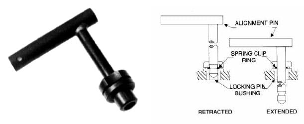
Figure 7-59. Locking alignment pins are positively retained in retracted position by a spring clip.
Quick-Release Alignment Pins
Quick-release pins are designed for applications that require frequent and rapid assembly and disassembly, featuring an integral locking mechanism in the pin itself that retains it in the hole. These alignment pins are highly suitable for modular fixtures that need to be quickly reconfigured or adjusted and in maintenance settings where components must be frequently removed or reinstalled.
Detent Pins
The simplest quick-release pin is the detent pin, shown in Figure 7-60. It has a simple spring-loaded dual-ball arrangement. The pin is simply pressed in or pulled out against light spring force, which extends the balls. Detent pins are available in either zinc-plated steel or stainless steel, while marine detent pins are made of 316 stainless steel for extra corrosion resistance. For economical solid alignment pins with a ground shank, this type of Detent Pin has a ring instead of a solid shoulder for applications where exact grip length is not important. Threaded detent pins are solid alignment pins made of 300 series stainless steel that feature a ground shank and a threaded end for a knob handle. The threaded end accepts virtually any type of knob handle, which can be made with steel, stainless steel, and several different plastics. Knob handles can be permanently secured with thread-locking adhesive if desired.
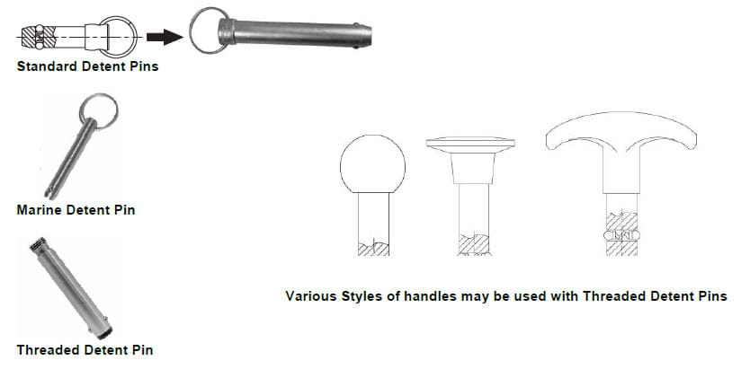
Figure 7-60. Detent pins are economical locating pins with spring-loaded locking balls.
Expanding Pins
Yet another type of quick-release pin is the expanding pin, highlighted in Figure 7-66. Expanding pins are precision alignment pins that expand up to .006” to tighten up hole clearance. The pin is an assembly of female split bushings separated by male segments on a center spindle that expands when drawn together. This assembly provides excellent shear strength comparable to a solid pin. Expanding pins are available in two versions, actuated either by a cam handle or by tightening with a wrench.
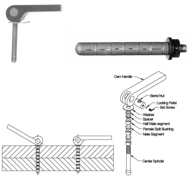
Figure 7-66. Expanding pins are precision, high-strength alignment pins that expand to tighten up hole clearance.
Ball Lock Pins
Another variation is the ball lock pin. This group includes single-acting ball lock pins, double-acting ball lock pins, adjustable ball lock pins, and lifting pins. These pins are similar to the detent type, except they have a positive ball locking mechanism to lock the pin in place with ease and security. Most ball lock pins are made of hardened steel or stainless steel for strength and corrosion resistance, and are extremely helpful in quickly locating, aligning, and fastening components.
Single-Acting Ball Lock Pins
Single-acting ball lock pins, shown in Figure 7-61, are installed and removed by pushing a button to unlock the balls. They are designed for quick and secure fastening in applications where only one-sided access is available. The release mechanism, usually a push button at the opposite end, allows for easy disengagement and removal. This type is particularly useful in tight spaces or where panels or components must be frequently removed and reattached, providing both convenience and time efficiency.
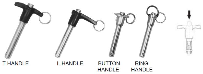
Figure 7-61. Single-acting Ball Lock Pins are precision alignment pins that are positively locked until released by pressing a button. They are available in four handle styles.
Double-Acting Ball Lock Pins
Double-acting ball lock pins, illustrated in Figure 7-62, have a locking mechanism that engages balls at both ends of the pin, securely fastening from both sides. These pins are released by either pulling or pushing the handle and are available with a “drive out” feature that allows you to remove the pin by driving it out of the hole with a hammer blow to the end of the activating spindle, which protrudes from the body of the pin for this purpose. Both single- and double-acting ball lock pins have a fixed grip length, ranging from ½” to 6” in one quarter inch increments. Special lengths are also available and made to order. Double-acting ball lock pins are particularly beneficial in applications that require alignment and locking through two opposing surfaces and in environments where robust and reliable fastening is critical, such as aerospace, automotive, and industrial manufacturing.
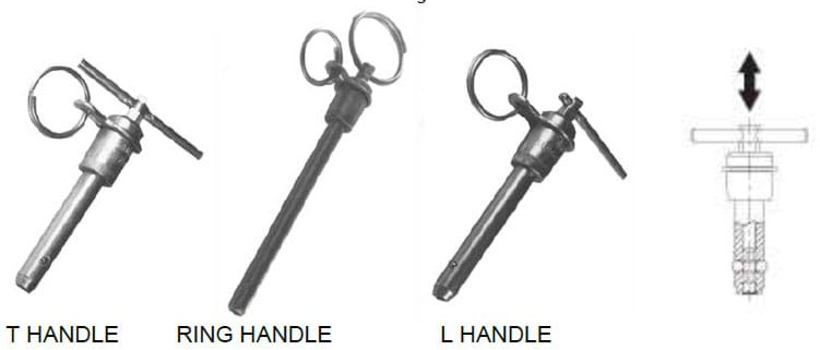
Figure 7-62. Double-acting ball lock pins are released by either pulling or pushing the handle. They are available in three handle styles.
Adjustable Ball Lock Pins
When grip length must be fine-tuned while in use, the adjustable ball lock pin can be used. This pin’s grip length is adjusted ±1/4” by turning the handle, then locked in place with a knurled lock nut. Marine ball lock pins are similar to standard single-acting ball lock pins in stainless steel, except this type has its handle and button made of 300-series stainless steel (instead of aluminum) for extra corrosion resistance in marine environments. Marine pins come in three handle styles: Button (B), Recessed Button (M), and Ring (R). Heavy duty ball lock pins have a larger, heavier handle for rough service and are only offered in stainless steel for maximum impact strength. They are also specially shaped to prevent accidentally pressing the release button.
Figure 7-63. Adjustable Ball Lock Pins are single-acting pins with a variable grip length. They are available in three handle styles.
In clevis applications, especially where the through-hole has excess clearance, it’s recommended to use ball lock receiver caps to secure ball lock pins. The receiver cap’s inside diameter fits the ball lock pin exactly and is stepped to provide a perfect locking surface for the balls. The receiver cap is tapped to fasten the terminal end of a standard ball lock pin cable assembly and includes a fastening screw for enhanced security. However, it’s essential to note that using a receiver cap reduces the ball lock pin's effective grip length, so this must be included in the grip length calculation before installation.
Lifting Pins
Another specialized single-acting ball lock pin is the lifting pin, shown in Figure 7-64. Lifting pins have a solid, one-piece body with four locking balls and a forged shackle for heavy lifting. These pins are typically used in manufacturing and construction environments for moving large, heavy, or awkwardly shaped items. They are secured by a locking mechanism that prevents accidental release under load, enhancing safety during lifting operations. However, as with all lifting devices, please observe the manufacturer’s instructions when using these components to maintain the safety of your equipment and team members.
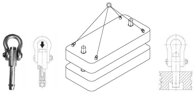
Figure 7-64. Lifting Pins are single-acting ball lock pins designed for heavy lifting, with a one-piece body, four locking balls, and a forged shackle.
The Carr Lock® System: A Combination Locator and Ball Lock Pin
The Carr Lock® System is a combination locator and clamp based on ball lock pin principles, allowing users to accurately locate and clamp at the same time with just the turn of a hex wrench. Each mount consists of three components:
- A Carr Lock® pin/clamp with a precisely ground shank
- A liner bushing in the top plate (plain or slotted)
- A receiver bushing in the subplate
Turning the clamping screw with a hex wrench advances the large center ball, pushing the three clamping balls outward. The combination of precision locating and quick-locking features enable their use for mounting tooling plates. The compact assembly of the Carr Lock® system provides considerable hold-down force alongside an incredible +/- .0005” repeatability.
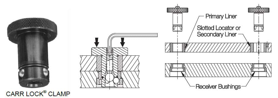
Figure 7-65. The Carr Lock® Mounting System incorporates ball lock principles to simultaneously locate and clamp, ideal for mounting quick-change tooling on a subplate.
Available Accessories for Alignment Pins
To simplify the attachment and removal process, there are a variety of accessories available for alignment pins. These additional tools can make it significantly easier to attach alignment pins and other items to a workholder, or to create a permanent assembly.
Cable Assemblies
Cable assemblies help secure alignment pins and other items to a workholder. Illustrated in Figure 7-67, cable assemblies attach directly to the workholder to ensure the items remain handy and less prone to loss or misplacement. Cable assemblies and their individual parts are available in many types, sizes, and lengths to suit almost every application, with various cable rings or tabs attached to either end.
Figure 7-67. Cable assemblies are handy for attaching alignment pins and other removable items to a workholder.
Nylon Lanyards
Nylon lanyards are designed for attaching to pins to prevent loss. The nylon lanyard has one eyelet end and one loop end (Figure 7-68) that snaps together for easy assembly. The eyelet end can be fastened with a screw, while the loop end is supplied open – simply snap together to create a permanent assembly. Snap assembly allows on-site attachment without a crimping tool, making these economical lanyards ideal for applications where the attached item is occasionally removed. Removal can be accomplished by cutting the lanyard, and to create a new assembly, the nylon lanyard can be replaced. They are made of Zylex high strength nylon and require a minimum pass-through diameter of 3/8" for attachment.
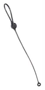
Figure 7-66. Nylon lanyards can be used to create permanent assemblies.
Coiled Lanyards
Coiled lanyards, made of polyurethane, are designed to maintain connection and prevent loss of pins. These lanyards feature an eyelet on one end for fastening with a screw and a split ring on the other to attach the pin. The coiled design allows the lanyard to stretch more than 10 times beyond its rest length, accommodating various positional needs and setups. Available in lengths of 3, 5, and 6 inches with a .11” wire diameter, these lanyards are ideal for applications where flexibility and distance variability are required.
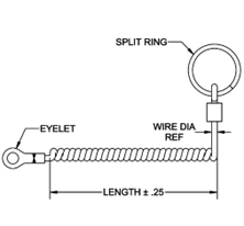
Figure 7-69. Coiled lanyards are flexible cords that can create permanent assemblies and prevent pin loss.
Find the Best Alignment Pins for Your Operation at Carr Lane Mfg.
Whether you’re creating a permanent assembly or need pins that can be easily removed and replaced, Carr Lane Mfg. offers a wide range of alignment pins to ensure you can accurately and securely align and position critical workholder components. To find the best pins for your application, we encourage you to explore our product catalog and discuss your unique needs with one of our experts.
Contact Carr Lane Mfg.