While fixed and adjustable locators are commonly used in jigs and fixtures, spring-loaded devices are also common solutions for workholding. They play an important role in the operation of many workholders, using a spring mechanism to apply consistent force or positioning to ensure accurate placement and retention of workpieces. Spring-loaded mechanisms are essential in reducing manual adjustment times and improving operational efficiency in production. Spring-loaded devices include spring locating pins, spring stop buttons, ball plungers, and spring plungers.
Spring Locating Pins
No matter how well a locating system is designed, mistakes can occur unless the parts are properly positioned against the locators every time. One device that reduces locating errors is the spring locating pin, shown in Figure 7-41.
Spring locating pins are equipped with a spring mechanism that allows the pin to retract under pressure and extend when released, pushing the part against the fixed locators. This ensures proper contact during the clamping operation and allows for easy alignment and insertion into workpiece holes. Although they’re not actually locating devices, the spring locating pins do help reduce errors by correctly positioning the part against the locators. In addition, the pins also eliminate the need for a “third hand” when clamping some parts. Their small size and compact design make them very useful for smaller parts or confined spaces and include a protective rubber seal around the contact pin to seal out chips and coolant.
Spring locating pins are typically made from hardened steel for maximum durability, allowing them to withstand repetitive use in industrial environments. They are also available in different sizes and spring tensions to accommodate various application needs, especially those that require frequent alignment and repositioning, such as modular assembly lines.
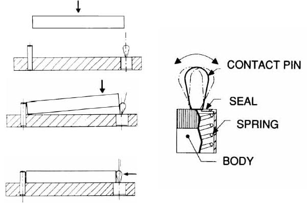
Figure 7-41. Spring locating pins push the workpiece against the fixed locators to ensure proper contact when the workpiece is clamped.
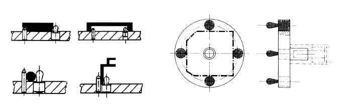
Figure 7-42. Spring locating pins are useful in many workholding applications.
Spring Stop Buttons
The spring stop button, illustrated in Figure 7-45, is another commonly used spring-loaded device. These units work much like the spring pins, but they are designed for larger parts or where more force is needed. They feature a spring mechanism that allows them to maintain or adjust position with a simple push, providing fast and reliable operation. When pressed, the button compresses the spring, allowing it to retract and clear a pathway or change positions. Once the button is released, the spring extends, positioning the button to stop or limit the movement of a component.
Spring stop buttons are made with three different contact faces. The first is a spherical button contact, and the other two have a flat contact. The flat-face contacts are made either with or without a tang, with flat-face tang contacts often being used for thin sheets. Carr Lane Mfg. spring stop buttons are made from high-strength materials such as steel or stainless steel to withstand repeated use and high-impact conditions in industrial environments, with various sizes, spring forces, and surface finishes available to suit specific operational needs.
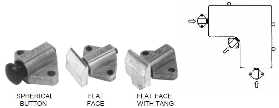
Figure 7-43. Spring stop buttons are another form of spring-loaded device. They are used to hold larger parts or when more force is needed.
Ball Plungers
Ball plungers are spring-loaded devices that consist of a ball encased in a housing with a spring behind it. They are used for a variety of workholding applications and are typically made from materials like stainless steel or brass, allowing for maximum durability and corrosion resistance. As shown in Figure 7-47, the ball plunger contains a hardened ball as a plunger. The spring exerts force on the ball, allowing it to retract and extend as pressure is applied or released. In many applications, the ball plunger is combined with a ball detent, which acts as a hardened locating and referencing device for the plunger. The ball plunger has a nylon-type locating element on the threads to prevent backing out after installation and is available in various sizes and spring tensions to accommodate different force requirements.
Ball plungers are commonly used in fixtures to position and hold components in place, ensuring they remain secure during machining or assembly processes. They also facilitate rapid assembly and disassembly, making them ideal for applications that require frequent adjustments or maintenance. They also can be used to locate workholder elements. For example, a ball plunger can locate an indexing arrangement by being mounted on a pin and held in place with a knurled knob. In this scenario, shown in Figure 7-45, the first hole is drilled, and the part is rotated until the ball plunger engages with the second ball detent. Once the ball plunger is engaged, the mandrel is locked, and the second hole is drilled.
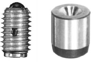
Figure 7-44. A ball plunger and matching ball detent.
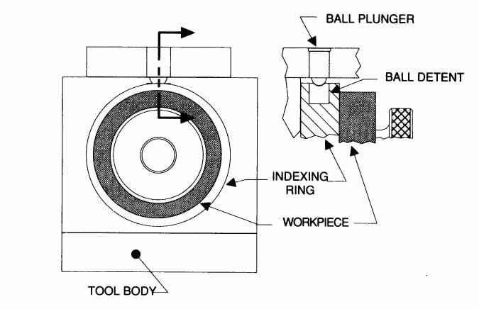
Figure 7-45. Ball plungers and ball detents are often used for indexing operations.
Spring Plungers
Spring plungers are like ball plungers, except with a longer stroke. Instead of a ball, the spring plunger has a cylindrical plunger with a rounded end, including a spring that compresses to allow the plunger to retract into the body and extend when released, providing controlled tension. Spring plungers are well suited for a variety of applications, such as the workpiece ejector shown in Figure 7-46, and come in various sizes, spring forces, and end configurations to suit specific application needs.
Spring plungers are also available in various lengths and end pressures, in either stainless or mild steel. These materials ensure spring plungers provide adequate strength, wear resistance, and consistent performance. They are also available with Delrin® plungers for applications where marring is a concern. Like ball plungers, spring plungers have a nylon-type locking element on the threads.
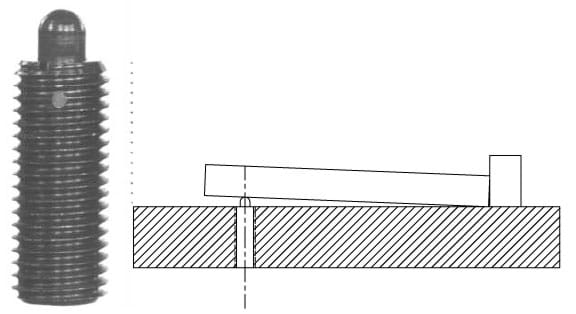
Figure 7-46. Spring plungers have a cylindrical plunger with a rounded end. They are sometimes used as part ejectors.
Hand-Retractable Plungers
Hand-retractable plungers, illustrated in Figure 7-47, are another style of spring plunger. Their purpose is to accurately align workholder elements. They are equipped with a handle or knob that manually controls the traction and extension of the plunger pin, allowing for easy and quick adjustments. Like ball plungers, hand-retractable plungers often provide indexing, but they engage an indexing hole rather than a ball detent. Such alignment both ensures the correct position and provides a positive lock. As shown in Figure 7-48, these plungers are hand-operated and must be pulled back to disengage the indexing hole. When the handle is released, a spring advances the plunger into the hole.
Hand-retractable plungers are typically made from durable materials such as steel or stainless steel to withstand repeated use, and come in various sizes and configurations, including different knob styles, to accommodate ergonomic preferences and application needs. The advantages of using hand-retractable plungers lie in the user control they provide, allowing for manual control over positioning to allow flexibility in assembly and maintenance tasks. They also facilitate fast changes and setups, increasing efficiency in production environments.
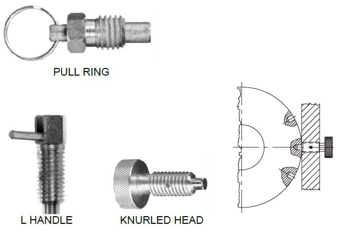
Figure 7-47. Hand-retractable plungers are spring-loaded plungers used to accurately align workholder elements in an indexing or referencing hole.
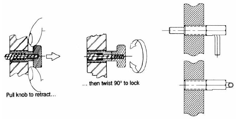
Figure 7-48. Hand-retractable plungers are advanced with a spring action and retracted manually.
Index Plungers and Bushings
Index plungers are precision, heavy-duty assemblies with a retractable spring-loaded plunger and a matching locating bushing. The spring-loaded pin locks into a corresponding notch or hole, allowing for precise positioning and alignment, with a handle or knob to retract the pin manually. Tapered index plungers feature a 15° taper on the plunger tip with a mating taper in the bushing, making alignment easier and eliminating any binding during retraction. The rotary-cam version completely retracts when the handle is rotated 180°, with cam surfaces made of hardened steel. The standard mount configuration shown in Figure 7-49 has a precision ground body with a whistle notch for orientation with a setscrew (also available with a slightly oversize unground body to allow custom grinding to size).
Bushings, often paired with index plungers, guide components for the plungers, ensuring smooth operation and alignment. They are typically made from materials like bronze, plastic, or steel to provide wear resistance and to reduce friction. Using bushings alongside index plungers helps distribute loads evenly in mechanical systems to extend the life of components and reduce noise, vibration, and wear in machinery.
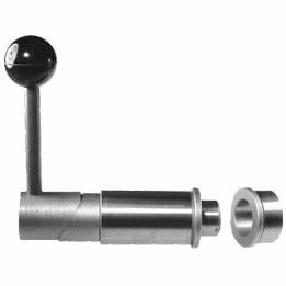
Figure 7-49. Standard mount style, with whistle notch for alignment.
Flange-Mount Configuration
The flange-mount index plunger configuration has a precision ground body with a flange used for orientation by fastening with two socket-head cap screws (also available with a slightly oversized unground body to allow custom grinding to size). Flange mounting is designed for installations where a cross hole for a set screw is not practical. This setup allows the plunger to be attached directly to surfaces where side mounting is unavailable and is particularly useful for applications requiring a secure, fixed positioning system in areas where space is limited.
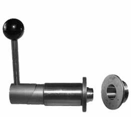
Figure 7-50. Flange-mount version of index plunger.
Straight Index Plunger with Blank Machinable End
This type of index plunger features a straight body design and an end that has not been pre-machined to specific dimensions or features. The blank machinable end allows the user to customize the end of the plunger to suit various actuating devices, including automated setups, providing flexibility in its use within different mechanical setups or machinery. Straight index plungers with blank machinable ends also feature a precision ground body (also available with a slightly oversized unground body to allow custom grinding to size).
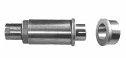
Figure 7-51. Straight index plunger with blank machinable end.
Find the Perfect Spring-Loaded Mechanism for Your Application at Carr Lane Mfg.
Spring-loaded mechanisms such as spring plungers, spring locating pins, spring stop buttons, and ball plungers play a crucial role in enhancing efficiency and precision across a variety of industrial applications. Their ability to provide consistent force and reliable positioning makes them indispensable in settings that demand accuracy and quick adjustments. Regardless of your operation, spring-loaded devices can help you enhance your assembly and manufacturing processes.
To integrate new components or enhance your productivity, explore our full range of spring-loaded devices today. Our experts can help you find the best solution for your operation and provide tailored recommendations to meet your unique needs. To discuss your specific jig and fixture needs, contact Carr Lane Mfg. today.